Fabrication method of diesel particular filter element

a technology of particular filter element and fabrication method, which is applied in the field of filter, can solve the problems of reducing the strength of the adjacent wire mesh layer, affecting the quality of the adjacent wire mesh, so as to achieve good precision

Inactive Publication Date: 2009-12-29
MITSUI ENG & SHIPBUILD CO LTD +1
View PDF12 Cites 5 Cited by
  • Summary
  • Abstract
  • Description
  • Claims
  • Application Information

AI Technical Summary

Benefits of technology

[0010]This invention takes the above-described problems into consideration and its objective is to provide a manufacturing method for a filter in which, in addition to being able to prevent telescoping more than has been possible up to now, its density is uniformly controlled with good precision.
[0012]According to this manufacturing method, because the wire mesh can be wound into a uniform configuration while maintaining its shape and the adjacent wire mesh layers are intertwined with each other increasing the strength, it is possible to prevent telescoping more than in the past. Furthermore, by changing the degree of compression, it is possible to control the apparent density of the filter uniformly with good precision over the entire filter and to effectively collect particulate matter.

Problems solved by technology

In recent years atmospheric pollution from particulate matter contained in the exhaust gases released in large amounts from diesel engines in such large-scale vehicles as busses and trucks has become a serious problem.
This particulate matter with minute carbon particles (soot) and unburned fuel as the principal components has a deleterious effect on health and restricting the amount of discharge into the environment has become a critical problem.
This filter is generally made by winding a belt-like wire mesh into a swirl body but this has the problem called telescoping in which the center part of the filter protrudes on the downstream side because of the pressure of the exhaust gases.
However, in the above-described invention, the wire mesh layers that are adjacent each other are lower in strength because they are only in contact and the problem of telescoping cannot be completely prevented.
Furthermore, because it is difficult to control the density of the filter uniformly with good precision, there is also the problem that the particulate matter cannot be effectively collected.

Method used


Image

  • Fabrication method of diesel particular filter element
  • Fabrication method of diesel particular filter element
  • Fabrication method of diesel particular filter element

Examples


embodiment

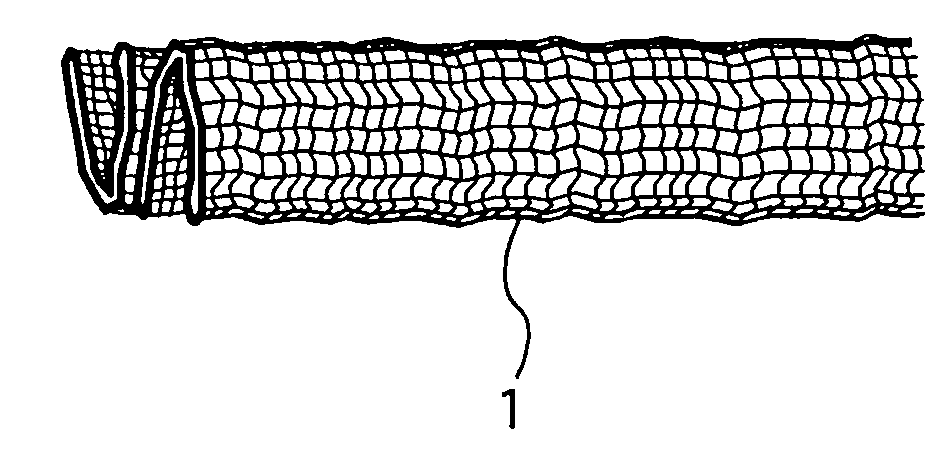
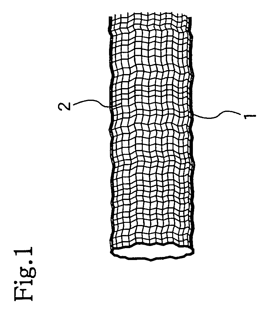
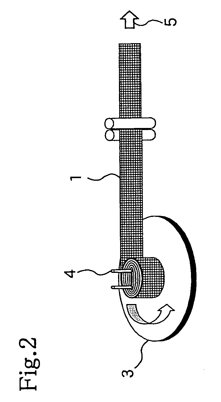
[0035]6 wires made of type 304 stainless steel with a diameter of 0. 12 mm were plain knitted and with the specifications shown in FIG. 1 a belt-like wire mesh with a width of 60 mm was manufactured. This wire mesh was halved and with the method shown in FIG. 2 wound into a swirl body while applying tensile stress until the outside diameter was 360 mm. The tensile stress as shown in Table 1 was changed in accordance with the size of the outside diameter of the filter.

[0036]

TABLE 1Filter outside diameter (mm)Tensile stress (N / m2)100 and below2.31 × 106100-2002.41 × 106200-3002.39 × 106300-3502.78 × 106

[0037]As shown in FIG. 8, the wire mesh wound in this manner was compressed with the addition of a 40 t pressure from above inside the molding die until the wire mesh height reached 60% and a filter was made with an apparent density of 1.35 g / cm3.

[0038]This filter was affixed to the exhaust gas purification device as shown in FIG. 10 and a purification test of the exhaust gas from a die...


PUM

PropertyMeasurementUnit
tensile stressaaaaaaaaaa
apparent densityaaaaaaaaaa
concentrationaaaaaaaaaa

Abstract

A diesel engine exhaust gas filter [8] is manufactured by winding a belt-like wire mesh [1] knitted from a metal wire [2] into a swirl body while being extended in the longitudinal direction and compressing it in the widthwise direction in a molding die. [6].

Description

BACKGROUND OF THE INVENTION[0001]This invention pertains to a filter for purifying the exhaust gas from a diesel engine and in particular pertains to a filter that removes particulate matter contained in the exhaust gas.DESCRIPTION OF RELATED ART[0002]In recent years atmospheric pollution from particulate matter contained in the exhaust gases released in large amounts from diesel engines in such large-scale vehicles as busses and trucks has become a serious problem.[0003]This particulate matter with minute carbon particles (soot) and unburned fuel as the principal components has a deleterious effect on health and restricting the amount of discharge into the environment has become a critical problem.[0004]As a result, technology has been developed for decreasing the amount of particulate matter released by putting a filter in diesel engines for collecting and removing the particulate matter.[0005]As an example of this filter Toyota et. al. have proposed a filter made of wire mesh tha...

Claims


Application Information

Patent Timeline
Patent Type & Authority Patents(United States)
IPC IPC(8): B01D39/00B01D39/06B01D39/08B01D39/14
CPCB01D39/086B01D39/12B01D46/24B01D46/528B01D46/0001B01D2239/0695
Inventor USHIKOSHI, JUNTAROIBARAGI, SHOICHIIMAI, KANEHISAOKUTANI, TOMOHIKO
Owner MITSUI ENG & SHIPBUILD CO LTD
Why Eureka
Try Eureka