Bus bar system with assembly unit consisting of a base plate and fixing items

a technology of assembly unit and assembly bar, which is applied in the direction of connection contact material, electrical apparatus casing/cabinet/drawer, coupling device connection, etc., can solve the problem of requiring a considerable assembly cost outlay, and achieve the effect of reducing manufacturing costs

Inactive Publication Date: 2009-12-29
RITTALWERK RUDOLF LOH GMBH & CO KG
View PDF12 Cites 4 Cited by
  • Summary
  • Abstract
  • Description
  • Claims
  • Application Information

AI Technical Summary

Benefits of technology

[0006]It is one object of this invention to reduce manufacturing costs for the assembly unit of a bus bar system of the type mentioned above, with a base plate and a fastening element produced as simple elements, which can be connected with each other by the most simple assembly without interfering with the requirements made on the assembly unit.
[0008]One advantage is that both parts, the base plate and the fastening element, can be produced in the form of simple profiled extruded elements and can be cut to any desired length. An identical fastening element can be used for both longitudinal sides of the base plate if the base plate is mounted and rotated by 180°. The covers and the device adapters can be used unchanged with the plug-in and / or snap-in receivers if the holding flanges of the base plate with the connected lateral legs of the fastening elements are designed as counter-elements for the plug-in and / or snap-in receivers of the covers and / or adapters.
[0011]The snap-in connection can be easily achieved after fixing in place if the snap-in protrusion at the lateral leg of the fastening element has a thickness, which continuously increases in the plug-in and / or snap-in direction and snaps into a snap-in receiver of a depth which decreases in this direction in the facing top of the fastening flange of the base plate.

Problems solved by technology

This requires complicated tools and, for reasons of cost, prevents a production in the form of a cut-to-size section of a profiled continuous piece.
However, a considerable assembly cost outlay is still required because the fastening elements must be connected with the base plate over the entire length of the bus bar system, and a fastening element must be attached to each longitudinal side of the base plate.

Method used


Image

  • Bus bar system with assembly unit consisting of a base plate and fixing items
  • Bus bar system with assembly unit consisting of a base plate and fixing items
  • Bus bar system with assembly unit consisting of a base plate and fixing items

Examples


Embodiment Construction

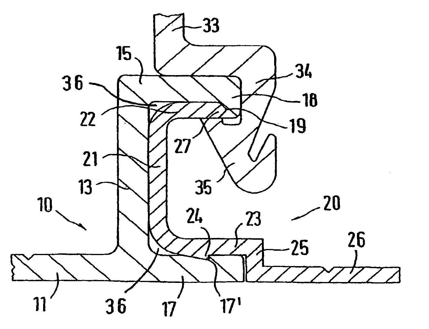
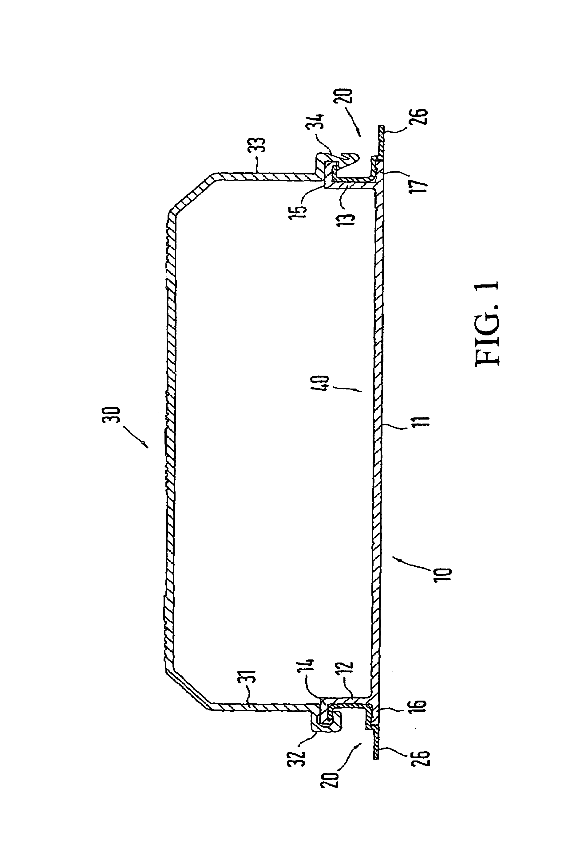
[0018]As the cross-sectional view in FIG. 1 shows, the base plate 11 with the two upward oriented lateral legs 12 and 13 forms a receiver 40 in a known manner, which extends over a defined length. This base plate 11 with the lateral legs 12 and 13, as well as holding flanges 14 and 15 projecting away from the exteriors of the lateral legs 12 and 13, as well as fastening flanges 16 and 17, is cut to a desired size from a profiled continuous piece.

[0019]Two-piece bus bar holders, in which bus bars are fixed in place, are inserted into the receiver 40. The unit including bus bars and bus bar holders is placed in a known manner into the receiver 40 of the assembly unit 10 and is therein fixed in place. It is thus not necessary to address the details of the fixation in place within the framework of this invention. New in connection with the assembly unit 10 is the application of the two fastening elements 20 on the two longitudinal sides of the base plate 11, which will be explained in d...


PUM


Abstract

A bus bar system with an assembly unit having a base plate with side limbs and fixing items which are connected to the assembly unit. The assembly unit forms a receiving element for a bus bar holder and bus bars which are covered with cover elements and / or adapters for peripheral devices. The covers and / or adapters are mechanically connected to the bus bars by plug-in receiving elements and / or locking receiving elements and the adapters are also electrically connected to the bus bars. An assembly unit, which can be produced and mounted at low cost without impeding functional requirements, is provided and the assembly unit forms locking receiving elements together with retaining flanges, which protrude at a distance on the outer sides of the side limbs, and fixing flanges, wherein bar-shaped fixing items can be inserted into and / or locked inside the receiving elements. The plug-in and / or locking receiving elements of the covers and / or adapters receive the retaining flanges and the connected side limbs of the bar-shaped fixing items.

Description

BACKGROUND OF THE INVENTION[0001]1. Field of the Invention[0002]This invention relates to a bus bar system with an assembly unit including a base plate with lateral legs and fastening elements which are connected with the assembly unit, wherein the assembly unit forms a receiver for bus bar holders and bus bars, which are covered by covers and / or adapters for devices to be connected, the covers and / or adapters are mechanically connected with the assembly unit by plug-in or snap-in receptacles, and the adapters are also electrically connected with the bus bars.[0003]2. Discussion of Related Art[0004]Bus bar systems are known from European Patent Reference EP 0 926 790 A3, European Patent Reference EP 0 926 791 A3 and German Patent Reference DE 93 06 013 U1. Here, the manufacture of the assembly unit from the assembly plate with fastening elements determines the costs of the bus bar system and it is possible to reduce costs if the base plate is combined in one piece with the fastening...

Claims


Application Information

Patent Timeline
Patent Type & Authority Patents(United States)
IPC IPC(8): H02G5/00H02B1/00H02G3/04
CPCH02G3/0418H02G3/04H02B1/20
Inventor WAGENER, HANS
Owner RITTALWERK RUDOLF LOH GMBH & CO KG
Why Eureka
Try Eureka