Inspection system using small catadioptric objective

a technology of catadioptric objective and inspection system, applied in the field of optical imaging, can solve the problems of high cost, difficult design of uv objective with good correction over field larger than 100 microns with 0.9 na, and limited system based on refractive objectiv

Active Publication Date: 2009-12-29
KLA TENCOR TECH CORP
View PDF61 Cites 4 Cited by
  • Summary
  • Abstract
  • Description
  • Claims
  • Application Information

AI Technical Summary

Benefits of technology

[0011]According to a first aspect of the present design, there is provided a system for inspecting a specimen. The system comprises an illumination system comprising an arc lamp able to provide light energy having a wavelength in the range of less than approximately 320 nanometers, and an imaging subsystem oriented and configured to receive the light energy from the illumination system and direct light energy toward the specimen, the imaging subsystem comprising a plurality of elements all aligned along a single axis, each element having diameter less than approximately 100 millimeters, wherein the imaging subsystem is configured to provide a field size in excess of approximately 0.4 millimeters at a numerical aperture of approximately 0.90 for the light energy received from the illumination system having the wavelength in the range of less than approximately 320 nanometers.
[0012]According to a second aspect of the present design, there is provided a system for inspecting a specimen. The system comprises an illumination system able to provide light energy having a wavelength within a predetermined range, and an illumination subsystem oriented and configured to receive the light energy from the illumination system and direct light energy toward the specimen, the imaging subsystem comprising a plurality of optical elements all aligned along an axis and each having maximum diameter less than approximately 100 millimeters, wherein the imaging subsystem is configured to provide a field size in excess of approximately 0.4 millimeters at a numerical aperture of approximately 0.90.
[0013]According to a third aspect of the present design, there is provided a system for inspecting a specimen. The system comprises an illumination system able to provide light energy having a wavelength within a predetermined range, and an imaging subsystem configured to receive the light energy and direct light energy toward the specimen using a plurality of elements having a maximum diameter less than approximately 100 millimeters, the plurality of elements being free of planar reflecting surfaces, wherein the imaging subsystem is configured to provide a field size in excess of approximately 0.4 millimeters at a numerical aperture of approximately 0.90.
[0014]According to a fourth aspect of the present design, there is provided a method for inspecting a specimen. The method comprises providing light energy having a wavelength within a predetermined range, and receiving the light energy and directing light energy toward the specimen using a plurality of optical elements aligned collectively along a single axis, each optical element having maximum diameter less than approximately 100 millimeters, wherein the optical elements are configured to provide a field size in excess of approximately 0.4 millimeters at a numerical aperture of approximately 0.90.

Problems solved by technology

Systems based on refractive objectives are limited due to imaging performance being typically capped at wavelengths above 365 nm.
Design of UV objectives having good correction over fields larger than 100 microns with 0.9 NA has also been difficult.
Such designs may have limitations including high cost, tight manufacturing tolerances, inflexible system architectures, and difficulty controlling contamination associated with DUV illumination.
Many of the aforementioned imaging systems have been constructed of relatively large components, which are difficult or impossible to employ in small environments, such as microscopes and the like.
The system disclosed therein offers certain imaging components and arrangements for inspecting specimens, but the designs disclosed therein cannot simply be used in all environments for imaging different types of specimens.
Inspection systems using different geometries, different light sources, with different performance criteria cannot use the designs of the Ser. No. 10 / 434,374 application to accurately and adequately assess specimen flaws under all circumstances.

Method used


Image

  • Inspection system using small catadioptric objective
  • Inspection system using small catadioptric objective
  • Inspection system using small catadioptric objective

Examples


Embodiment Construction

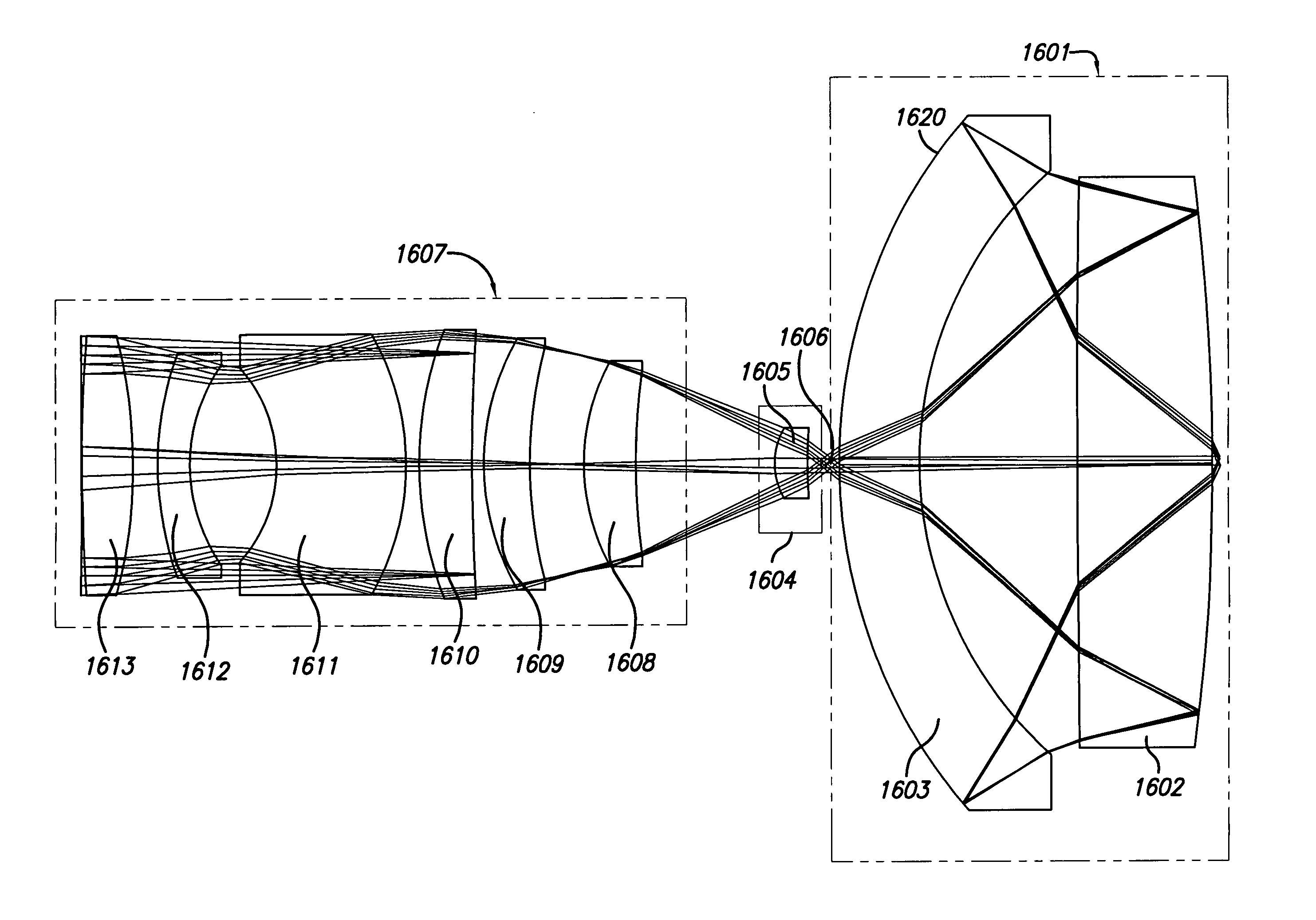
[0069]The inspection system and designs disclosed herein employ an imaging subsystem having generally small size, in particular a small sized objective design, that provides advantages over previous catadioptric designs. The present inspection system provides various components and subsystems that may be employed in accordance with a relatively small objective to provide accurate and high quality scans as compared with previously known systems employing relatively small objectives.

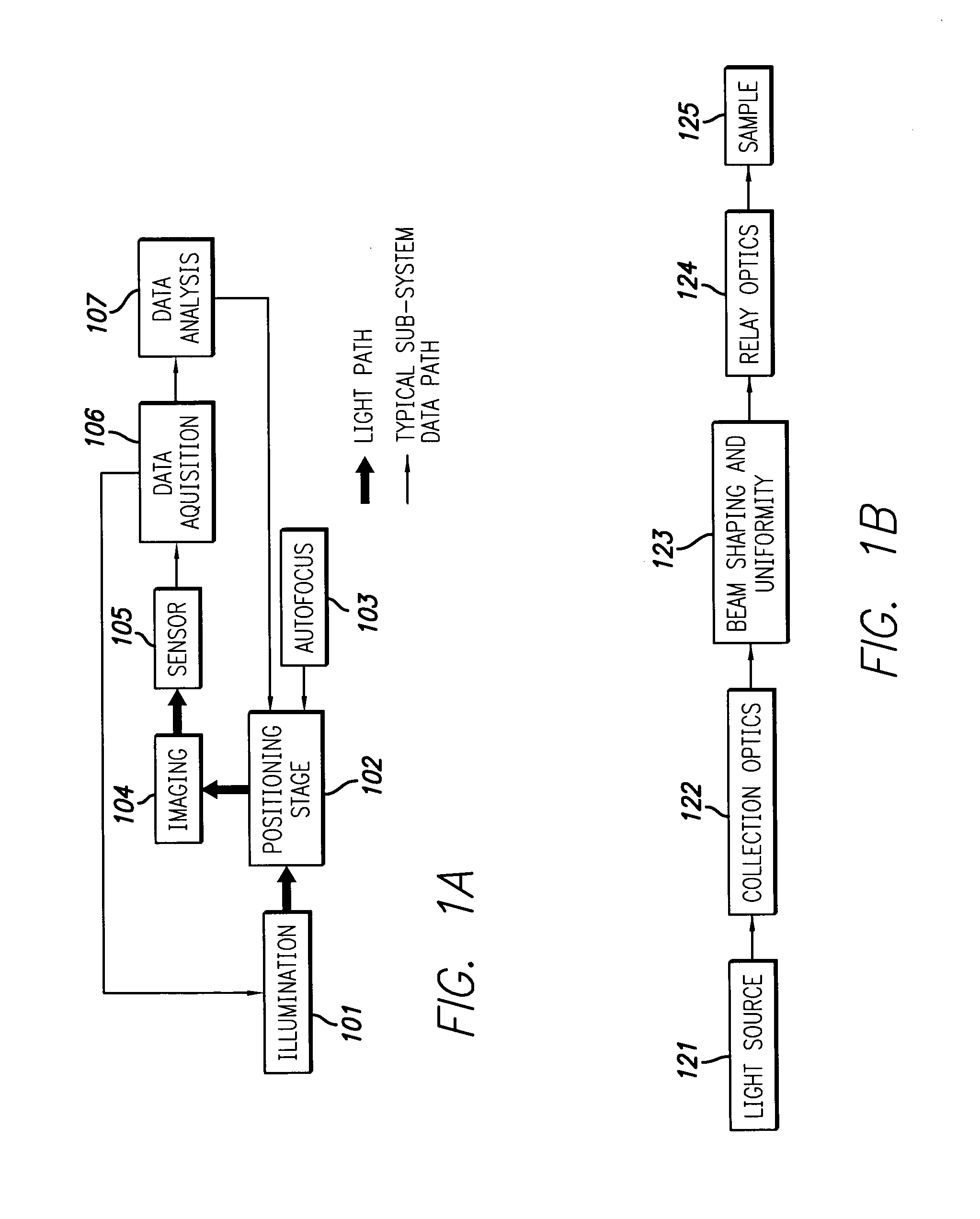
[0070]FIG. 1A illustrates a typical inspection system having an illumination subsystem 101, positioning stage 102, autofocus subsystem 103, imaging subsystem 104, sensor subsystem 105, data acquisition subsystem 106, and data analysis subsystem 107. The objective in the present design is embodied in the imaging subsystem 104 and will be discussed in detail below. In the arrangement of FIG. 1, light travels via the light path shown from the illumination subsystem 101 to the positioning stage 102, the imagin...


PUM

PropertyMeasurementUnit
wavelengthaaaaaaaaaa
diameteraaaaaaaaaa
diameteraaaaaaaaaa

Abstract

A system for use with a reduced size catadioptric objective is disclosed. The system including the reduced size objective includes various subsystems to allow enhanced imaging, the subsystems including illumination, imaging, autofocus, positioning, sensor, data acquisition, and data analysis. The objective may be employed with light energy having a wavelength in the range of approximately 190 nanometers through the infrared light range, and elements of the objective are less than 100 mm in diameter. The objective comprises a focusing lens group and at least one field lens oriented to receive focused light energy from the focusing lens group and provide intermediate light energy. The objective also includes a Mangin mirror arrangement. The design imparts controlled light energy with a numerical aperture in excess of 0.65 and up to approximately 0.90 to a specimen for imaging purposes, and the design may be employed in various environments.

Description

[0001]This application is a continuation-in-part of U.S. patent application Ser. No. 10 / 434,374, filed May 7, 2003, entitled “High Performance Catadioptric Imaging System,” inventors Shafer et. al., which claims the benefit of U.S. Provisional Patent Application Ser. No. 60 / 449,326, entitled “High Performance, Low Cost Catadioptric Imaging System,” filed Feb. 21, 2003.BACKGROUND OF THE INVENTION[0002]1. Field of the Invention[0003]The present invention relates generally to the field of optical imaging and more particularly to optical systems for microscopic imaging, inspection and / or lithography applications.[0004]2. Description of the Related Art[0005]Many optical systems and electronic systems are available to inspect surface features of a specimen for defects., including specimens such as a partially fabricated integrated circuit. Defects on such specimens may be relatively small in size and may take the form of imperfections randomly localized on the specimen surface, such as pa...

Claims


Application Information

Patent Timeline
Patent Type & Authority Patents(United States)
IPC IPC(8): G02B17/08G01N21/88G01N21/95G02BG02B5/00G02B17/00G02B21/02G03F7/20
CPCG01N21/8806G02B17/0808G03F7/70341G02B17/0856G02B17/0892G02B21/02G03F7/70225G02B17/0812G01N21/9501G02B5/001
Inventor CHUANG, YUNG-HOARMSTRONG, J. JOSEPHSHAFER, DAVID R.
Owner KLA TENCOR TECH CORP
Why Eureka
Try Eureka