Method and apparatus for operating AC powered appliances via video interphones, two way IR drivers and remote control devices

a technology of ac powered appliances and video interphones, applied in the field of video interphone systems and wired or wireless control, can solve the problems of inability to positively verify the on-off power status without, high cost of ac electrical wiring customization, and high cost of on-off switching devices, so as to effectively close the missing link and low cost

Inactive Publication Date: 2009-12-29
ELBEX VIDEO LTD
View PDF16 Cites 141 Cited by
  • Summary
  • Abstract
  • Description
  • Claims
  • Application Information

AI Technical Summary

Benefits of technology

[0023]Another object of the present invention is to use the two way IR communication in conjunction with the add on relays and the current sensor of the AC outlets, to effectively close the missing link between AC operated appliances that are remotely activated by IR remote control devices, but do not provide a return command confirmation or status to the remote control device, nor to the home automation controller, including the video interphone and the shopping terminal. This is achieved by the use of a low cost two way IR remote control devices and two way adjustable IR drivers, employing common codes adapted for the entire appliances of a given system including lighting and other AC on-off operated devices and all the IR activated electronic appliances, by providing a simple look up table programmed for the home automation controller, which converts the received common codes into the codes as used for the non compatible, individual appliances that are located in the different rooms or areas of the home, on the basis of an allotted code to a given room or area in the home, office or building and the code allotted to each individual appliance as programmed by using the adjustable IR driver to optically direct the IR command to the appliances as programmed.

Problems solved by technology

Most of the remote control devices, including IR or wireless remote control devices use the same power key to switch the appliance on and off, therefore without the operating person's self verification on site, with most of currently available remote control devices it is impossible to positively verify the on-off power status without being at the appliance site.
The problem such system represents is the cost for customizing of the AC electrical wiring, coupled with the on-off switching devices which are expensive and require expertise to configure, install and setup.
The introduction of new electrical wirings and new switches and outlets to replace the currently available electrical switches and outlets is complicated, time consuming, troublesome and costly.
The testing and approval processes are costly and time consuming, which makes approvals of customs designed AC electrical switches, AC electrical outlets and AC electrical interfaces for home automation out of reach to the mass market, limiting the proliferation of the much needed home automation to only custom designed AC switches, outlets and interfaces, for use in very expensive homes.
The problem however for such remote controlling is the need for a verified on-off status of the appliances being operated and / or the availability of a status report covering all the remotely controlled appliances of a given house, office, apartment or a building.
This combination of non compatibility in commands, codes, protocols, frequencies and others on one hand, and with no receiving function to confirm the basic on-off status of the appliance on the other, makes it impossible to integrate standard appliances into an error free home automation system operated from a distance, such as via the Internet.
Moreover, the known appliances do not include an IR transmitter to generate return confirmation, such as an executed command, nor do the appliances provide an on-off or other AC current drain status data via IR or other communications.

Method used


Image

  • Method and apparatus for operating AC powered appliances via video interphones, two way IR drivers and remote control devices
  • Method and apparatus for operating AC powered appliances via video interphones, two way IR drivers and remote control devices
  • Method and apparatus for operating AC powered appliances via video interphones, two way IR drivers and remote control devices

Examples


Embodiment Construction

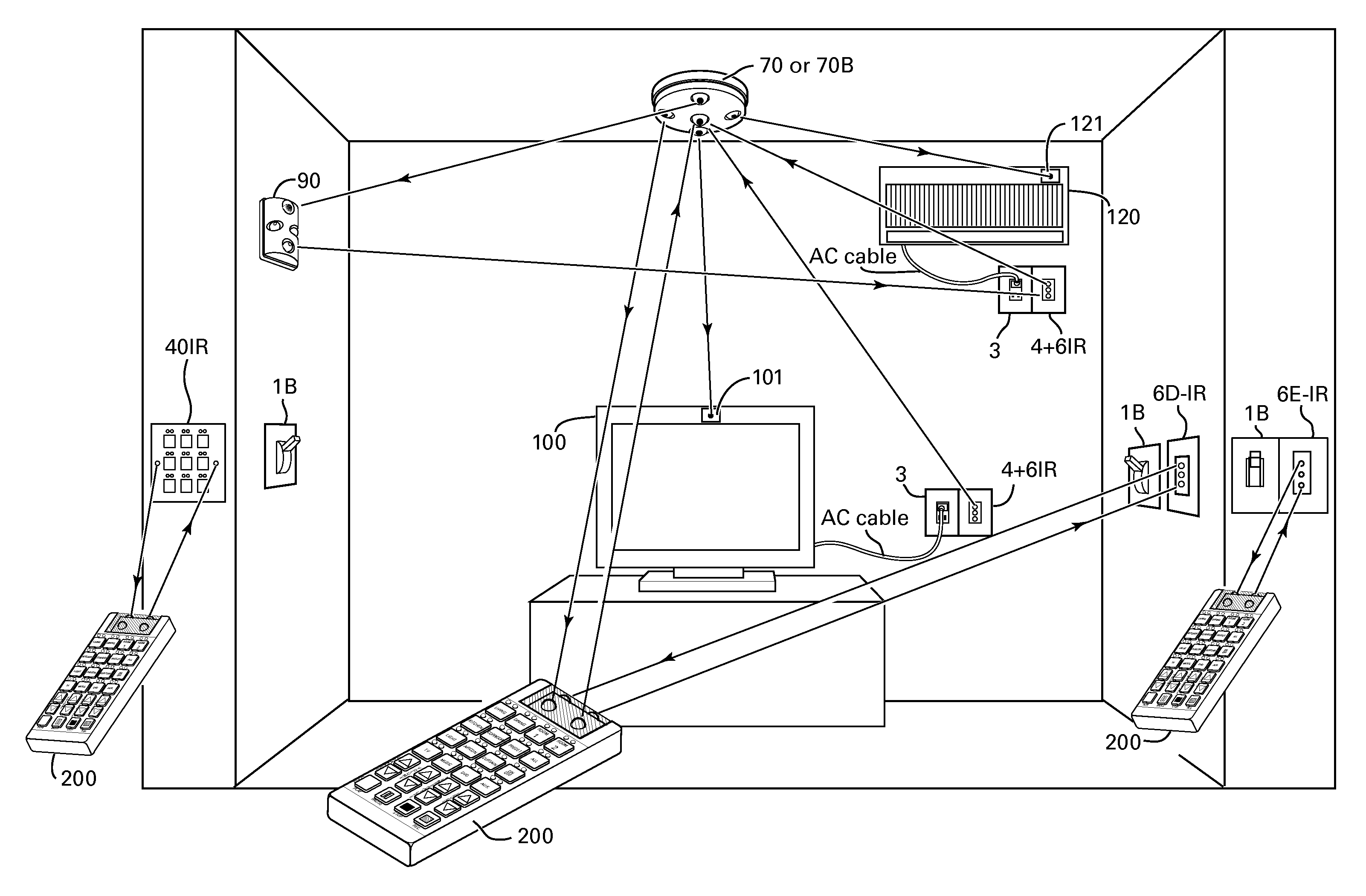
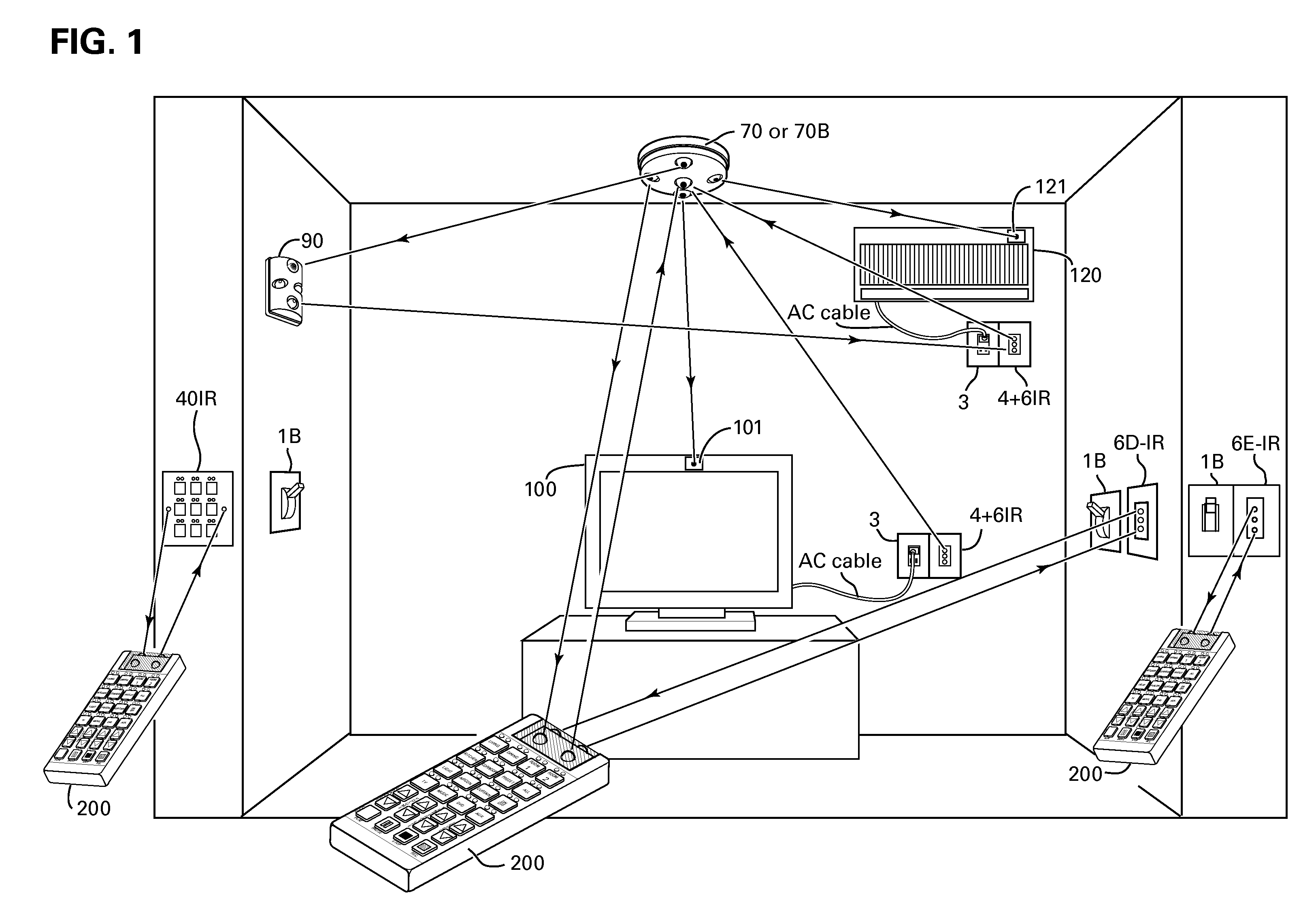
[0038]Shown in FIG. 1 is an IR network of an home automation system that includes electrical switches for operating electrical appliances, such as light fixtures (not shown), a television set 100 and an air conditioner 120. The AC power cables of both the television set 100 and the air conditioner 120 are shown connected to AC outlets 3 with each of the outlets is adjacent to an AC current sensor unit 4+6IR for detecting the on-off status of the television set 100 and the air conditioner 120 individually. The electrical on-off switches 1B shown in FIG. 1 are the well known standard single pole dual throw (SPDT) switches also known as “switch over” that are commonly used for operating a given appliances such as light fixture (not shown) from two separate locations. Two of the three SPDT switches 1B shown are adjacent to an add on relay units 6D-IR and 6E-IR.

[0039]The relay units also include an AC current sensor for detecting the on-off status of the operated AC appliance. The curren...


PUM


Abstract

A method for coupling at least one of a wall mount and a ceiling mount adjustable IR driver with a two way IR network of a home automation system controlled by a main controller selected from a group comprising a dedicated controller, a video interphone and a shopping terminal, the IR driver includes a plurality of adjustable IR transmitters and at least one IR receiver for propagating IR commands to at least one of hand held IR remote control units, electrical appliances and devices selected from a group comprising a remotely operated relays, an AC current sensors and a keypads, and for receiving from at least one of the devices a status data, said IR commands include at least a power on-off command for switching an appliance on and off and the status data pertaining to the on and off statuses of a commanded appliance.

Description

BACKGROUND OF THE INVENTION[0001]1. Field of the Invention[0002]This invention is related to video interphone system and to wired or wireless control, including IR and RF, used for remotely operating AC switches and AC powered electrical devices and appliances.[0003]2. Description of the Prior Art[0004]Wired or wireless remote control devices including InfraRed (IR) or RF transmitter for remotely operating AC powered electrical appliances such as television receivers, home heaters, air conditioners, motorized curtains, lighting and other electrical appliances in homes, apartments, offices and buildings in general are switched on and off by a one way control or command signal, with the person operating the remote control device verifying the on or off status of the operated device by visual means, such as the TV is on, or the lights are off, or the air condition unit is activated or not, by being at the site of the operated appliance. Most of the remote control devices, including IR ...

Claims


Application Information

Patent Timeline
Patent Type & Authority Patents(United States)
IPC IPC(8): G02B6/28
CPCG08C17/02G08C23/04G08C2201/50G08C2201/40
Inventor ELBERBAUM, DAVID
Owner ELBEX VIDEO LTD
Why Eureka
Try Eureka