End effector assembly for supporting a substrate

a technology of end effector and substrate, which is applied in the direction of charge manipulation, hoisting equipment, furnace, etc., can solve the problems of undesirable melted rubber stuck to the backside of the substrate, several high temperature rubber compounds available, and the conventional transfer robot is not suited for such high temperatures. , to achieve the effect of enhancing the capture of the substrate and minimizing the slippage of the substra

Inactive Publication Date: 2010-01-05
APPLIED MATERIALS INC
View PDF39 Cites 27 Cited by
  • Summary
  • Abstract
  • Description
  • Claims
  • Application Information

AI Technical Summary

Benefits of technology

[0007]In one aspect of the invention, an end effector assembly for a substrate transfer robot is provided. Generally, an end effector assembly for a substrate transfer robot is provided. In one embodiment, an end effector assembly for supporting a quadrilateral substrate during substrate transfer includes an end effector having an inner edge support disposed on a first end and a first outer edge support disposed on a distal end. The first end of the end effector is adapted for coupling to a robot linkage. The first inner edge support has a face that is oriented parallel to and facing the face of the first outer edge support. This configuration of edge supports captures the substrate to the end effector thereby minimizing substrate slippage during transfer. In another embodiment, lateral guides may be utilized to further enhance capturing the substrate along the edges of the substrate open between the inner and outer edge supports.

Problems solved by technology

Generally, conventional transfer robots are not suited for operation at such high temperatures.
Several high temperature rubber compounds are available but are typically limited to a maximum operating temperature of about 320 degrees Celsius, significantly lower than the 550 degrees Celsius desired in polysilicon heat treating processes.
When the end effector of the robot is exposed to high temperature for more than ten seconds, these conventional rubber pads typically melt and stick to the substrate.
The melted rubber stuck to the backside of the substrate is undesirable both due to potential contamination and subsequent processing issues.
Moreover, once the rubber pad is removed from the end effector, scratching of the backside of the substrate by the end effector may occur which may lead to particulate generation and substrate damage or breakage.
Furthermore, if the rubber pad melts, replacement of the pad is difficult.

Method used


Image

  • End effector assembly for supporting a substrate
  • End effector assembly for supporting a substrate
  • End effector assembly for supporting a substrate

Examples


Embodiment Construction

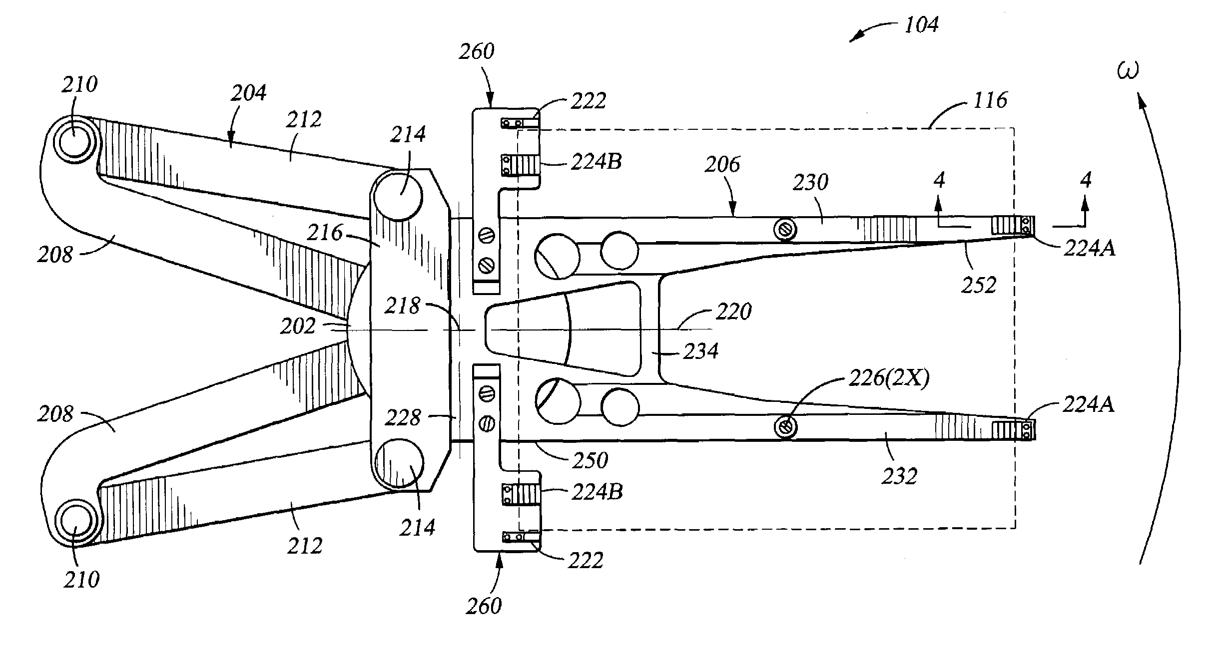
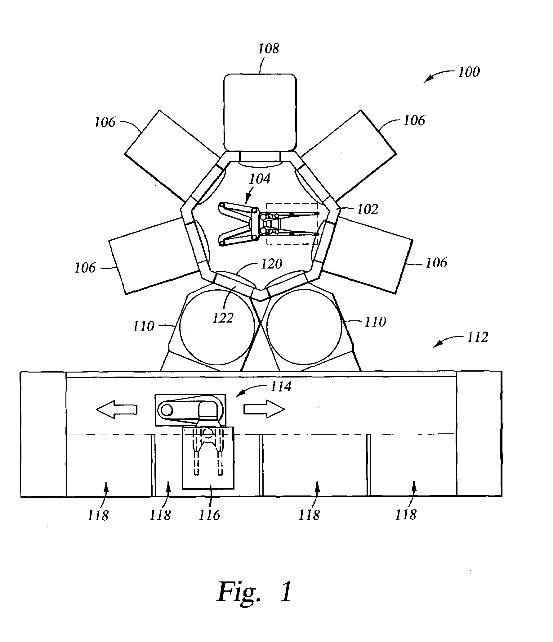
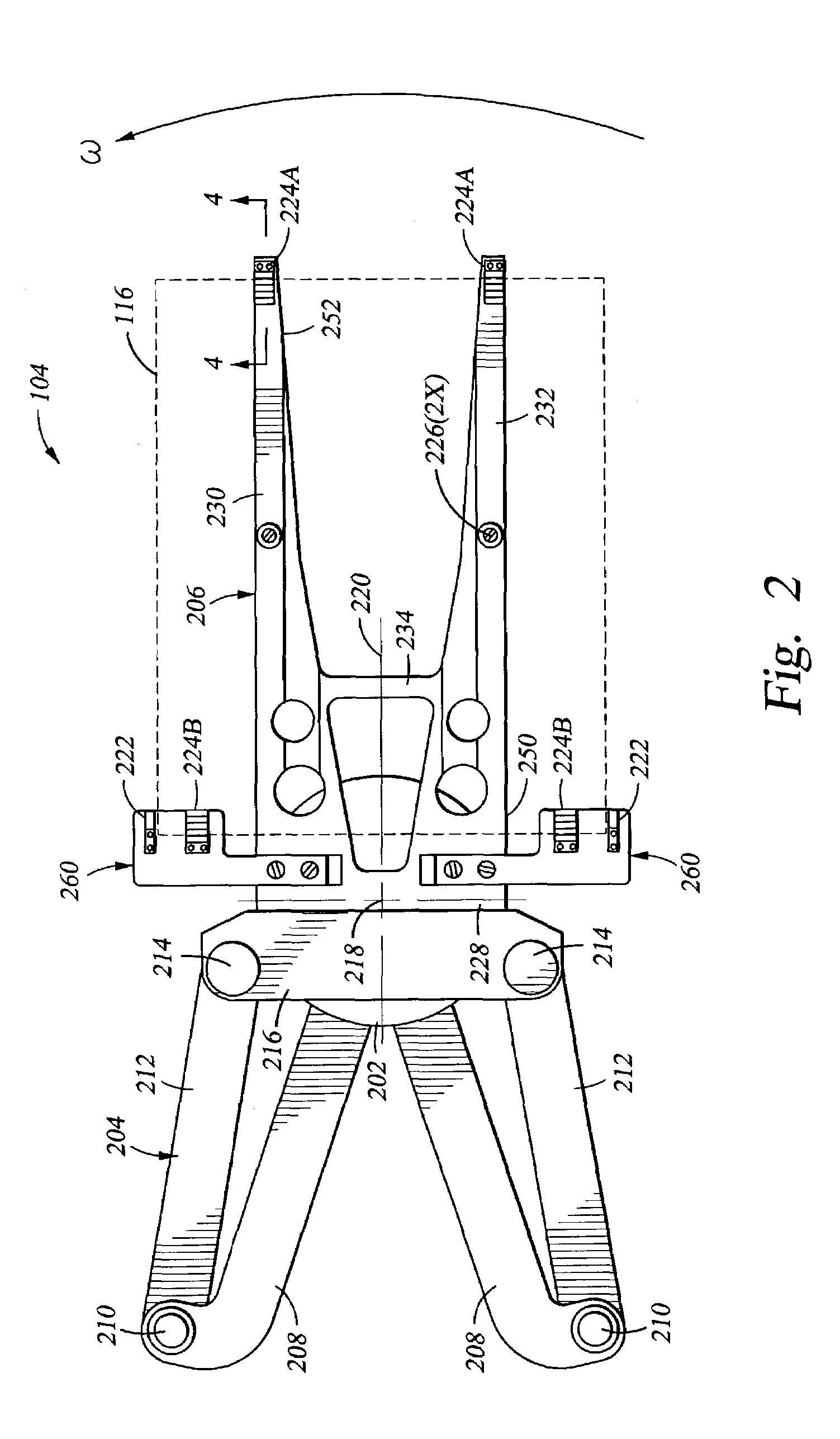
[0019]FIG. 1 depicts a schematic layout of a cluster tool 100. The cluster tool 100 generally comprises a transfer chamber 102 having a first transfer robot 104 disposed therein. The transfer chamber 102 is surrounded by a plurality of processing chambers 106, a thermal processing chamber 108 and at least one load lock chamber 110. The load lock chambers 110, two of which are depicted in FIG. 1, are generally coupled between the transfer chamber 102 and a factory interface 112. One cluster tool that may be adapted to benefit from the invention is available from AKT, Inc., a wholly-owned division of Applied Materials, Inc., located in Santa Clara, Calif.

[0020]The factory interface 112 generally includes a second transfer robot 114 that transfers substrates 116 between the load locks 110 and a plurality of wafer storage cassettes 118 coupled to or disposed within the factory interface 112. The second transfer robot 114 may be configured similar to the first transfer robot 104 describe...


PUM


Abstract

Generally, an end effector assembly for a substrate transfer robot is provided. In one embodiment, an end effector assembly for supporting a quadrilateral substrate during substrate transfer includes an end effector having an inner edge support disposed on a first end and a first outer edge support disposed on a distal end. The first end of the end effector is adapted for coupling to a robot linkage. The first inner edge support has a face that is oriented parallel to and facing the face of the first outer edge support. This configuration of edge supports captures the substrate to the end effector thereby minimizing substrate slippage during transfer. In another embodiment, lateral guides may be utilized to further enhance capturing the substrate along the edges of the substrate open between the inner and outer edge supports.

Description

BACKGROUND OF THE INVENTION[0001]1. Field of the Invention[0002]Embodiments of the invention relate to an end effector assembly for supporting substrates.[0003]2. Background of the Related Art[0004]Thin film transistors (TFTs) are conventionally made on large glass substrates or plates for use in monitors, flat panel displays, solar cells, personal digital assistants (PDAs), cell phones and the like. TFTs are made in a cluster tool by sequential deposition of various films including amorphous silicon, doped and undoped silicon oxides, silicon nitride and the like in vacuum chambers typically disposed around a central transfer chamber. Production of good quality polysilicon precursor films utilized in these structures requires that the hydrogen content of the film be controlled below about 1 percent. In order to achieve this low hydrogen content, post deposition heat treatment of the film at temperatures of about 550 degrees Celsius is required.[0005]Accordingly, robots utilized to m...

Claims


Application Information

Patent Timeline
Patent Type & Authority Patents(United States)
IPC IPC(8): B25J15/00B65G49/07H01L21/687
CPCH01L21/68707Y10S414/141Y10S294/902B65G49/062H01L21/67742H01L21/68721H01L21/68735
Inventor BLONIGAN, WENDELL T.MATSUMOTO, TAKAYUKISTERLING, WILLIAM N.LEUNG, BILLY C.
Owner APPLIED MATERIALS INC
Why Eureka
Try Eureka