Mechanical chain tensioner with compliant blade spring

a technology of blade springs and tensioners, which is applied in the field of tensioners, can solve problems such as chain tension fluctuations, damage or rendering the engine inoperative, and chain tension to vary between excessively high or low levels

Active Publication Date: 2010-01-05
BORGWARNER INC
View PDF50 Cites 15 Cited by
  • Summary
  • Abstract
  • Description
  • Claims
  • Application Information

AI Technical Summary

Problems solved by technology

Prevention of such slippage is particularly important in the case of a chain driven camshaft in an internal combustion engine because jumping of teeth will throw off the camshaft timing, possibly causing damage or rendering the engine inoperative.
However, in the harsh environment of an internal combustion engine, various factors can cause fluctuations in the chain tension.
For instance, wide variations in temperature and thermal expansion coefficients among the various parts of the engine can cause the chain tension to vary between excessively high or low levels.
During prolonged use, wear to the components of the power transmission system can cause a decrease in chain tension.
In addition, camshaft and crankshaft induced torsional vibrations cause considerable variations in chain tensions.
Reverse rotation of an engine, occurring for example in stopping or in failed attempts at starting, can also cause fluctuations in chain tension.
In such a fashion, the tensioner achieves a so-called no-return function, i.e., movements of the plunger are easy in one direction (outward) but difficult in the reverse direction.
One of disadvantages of the tensioning device of U.S. Pat. No. 6,599,209 is the spring only tensions the center of the tensioning track and not along the entire face of the tensioner.
Another disadvantage is the assembly required to place the spring within the supporting body, since the tensioner is one piece.

Method used


Image

  • Mechanical chain tensioner with compliant blade spring
  • Mechanical chain tensioner with compliant blade spring
  • Mechanical chain tensioner with compliant blade spring

Examples


first embodiment

[0039]FIGS. 7 through 9 show the tensioner of a first embodiment with a new chain 500 wrapped around a drive sprocket and a driven sprocket (not shown). On the outside of the slack strand is tensioner 601.

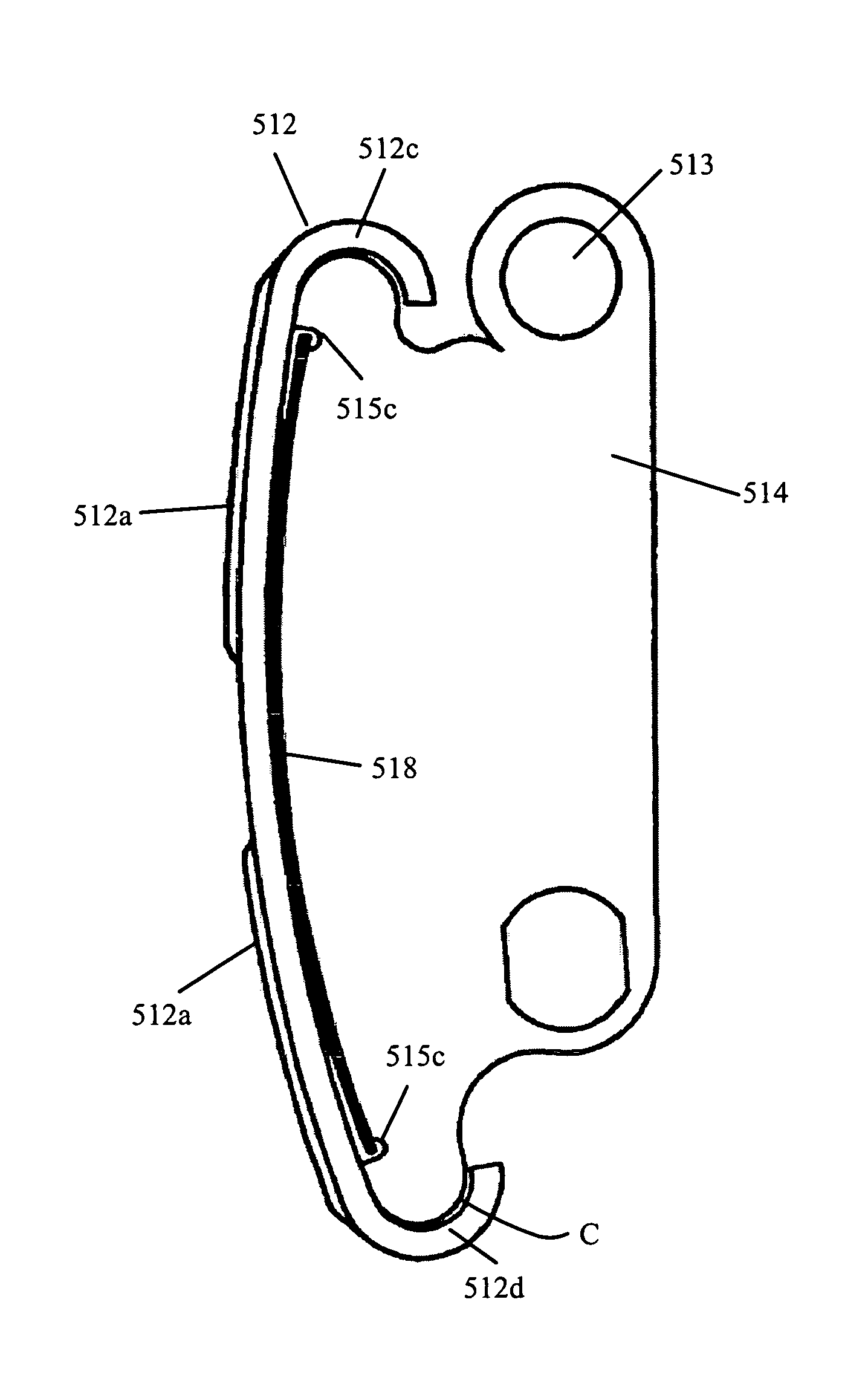
[0040]Referring to FIGS. 9 and 12, a bracket body 514 has a surface 514c with a curved profile that is similar to the path of a new chain as controlled by the chain guide element 512. A channel cut groove 515 with sides 515a, a bottom 515b and recessed pockets 515c at either end of the groove 515 is found longitudinally along the length of the surface 514c. At least one blade spring 518, see FIG. 14, is somewhat flattened and placed in the channel cut groove 515. The blade spring 518 is a rectangle curled lengthwise in its free state and applied mostly uncurled in its assembled state, in the channel cut groove 515, between the bracket body 514 and the chain guide element 512. The recessed pockets 515c at either end of the groove 515 act as containment means and bearing surfaces for...

second embodiment

[0049]Alternatively, when two tensioners 601, 701 are present, as in the second embodiment, the spring rate of the blade springs may be different. In one example, to tension the chain slack on one side (the slack side) only, the chain guide element 512 on the tight strand would normally be against the stop 514c of the bracket body 514. In the event of a load reversal due to torsionals or the reverse rotation that can occur at stopping of an internal combustion engine, the slack and tight strands are reversed and the tensioner on the tight strand would respond by tensioning the slack and preventing the bunching of the chain at the driven sprocket that contributes to tooth jumping when normal chain rotation is resumed. The possibly weaker spring on the tight strand also softens the impact when the chain again resumes its normal tight path and chain guide element 512 reseats on bracket body 514.

[0050]In another example, to tension the chain slack on both strands equally, the blade spri...


PUM


Abstract

A tensioner for imparting tension to a chain having a body, a resilient chain guide element, at least one blade spring, and at least one bracket. The body of the tensioner has a surface with a profile of the path of a new chain and a groove found longitudinally along the length of the surface. The resilient chain guide element, on the surface of the body has a chain contact surface and two ends wrapped around the ends of the body, with the chain guide being sufficiently larger than the body, such that the chain contact surface is capable of being biased away from the body. The blade spring is present in the groove with its end in the containments means of the groove, biasing the chain guide out and away from the body.

Description

REFERENCE TO RELATED APPLICATIONS[0001]This application is related to an application filed simultaneously, entitled “PIVOTING MECHANICAL BLADE TENSIONER WITH COMPLIANT BLADE SPRING”. The aforementioned application is hereby incorporated herein by reference. The application is also related to application Ser. No. 10 / 984,450 filed Nov. 9, 2004, entitled “COMPLIANT SNUBBER” and application Ser. No. 10 / 692,182 filed Nov. 9, 2004, entitled “Complaint Chain Guide With Blade Spring.” The aforementioned applications are hereby incorporated by reference.BACKGROUND OF THE INVENTION[0002]1. Field of the Invention[0003]The invention pertains to the field of tensioners. More particularly, the invention pertains to a mechanical tensioner with a compliant blade spring.[0004]2. Description of Related Art[0005]A tensioning device, such as a hydraulic tensioner, is used as a control device for a power transmission chain, or similar power transmission devices, as the chain travels between a plurality ...

Claims


Application Information

Patent Timeline
Patent Type & Authority Patents(United States)
IPC IPC(8): F16H7/08
CPCF16H7/08F16H7/18F16H2007/0874F16H2007/0872F16H2007/0804
Inventor MARKLEY, GEORGE L.CROCKETT, II, JOHN T.TURNER, TIMOTHY A.
Owner BORGWARNER INC
Why Eureka
Try Eureka