Method, apparatus, and system for image guided bone cutting

a technology of image guided bone cutting and cutting path, which is applied in the field of surgical removal of bone portions, can solve the problems of femur and tibia, pain for patients, and reduced mobility, and achieve the effect of accurate cutting path placement and greater accuracy

Active Publication Date: 2010-01-05
BIOMET MFG CORP
View PDF265 Cites 138 Cited by
  • Summary
  • Abstract
  • Description
  • Claims
  • Application Information

AI Technical Summary

Benefits of technology

[0005]The present system further provides a cutting block having a frame, a guide adjustably connected to the frame, an adjustor connected to the frame, and mounting locations defined by the frame and configured to attach to the bone at the target locations. The mounting locations include either bores for receiving the pins that were inserted into the target locations, or pins for insertion into the bores that were created using the image guided drill cylinder. Accordingly, the cutting block can be accurately placed on the bone at the target locations, which in turn accurately places the guide.
[0007]Additionally, the present system may include a tracking instrument having an element configured to be detected by the image guidance system and an engagement portion configured to engage the cutting path to permit image guided adjustment of the cutting path. Thus, in addition to providing accurate placement of the cutting path using the image guide drill cylinder to locate the mounting locations of the cutting block, the present system enables the surgeon to achieve even greater accuracy by providing image guided adjustment of the cutting path when the cutting block is mounted to the bone.

Problems solved by technology

Without such precision mating, the reconstructed knee may result in misalignment (alignment that differs from optimal alignment corresponding to the patient's physical characteristics) of the femur and the tibia.
Such misalignment may have a variety of undesirable consequences including discomfort to the patient, reduced mobility, and excessive wear on surfaces of the prostheses.

Method used


Image

  • Method, apparatus, and system for image guided bone cutting
  • Method, apparatus, and system for image guided bone cutting
  • Method, apparatus, and system for image guided bone cutting

Examples


Embodiment Construction

[0022]While the present system is susceptible to various modifications and alternative forms, exemplary embodiments thereof have been shown by way of example in the drawings and will herein be described in detail. It should be understood, however, that there is no intent to limit the system to the particular forms disclosed, but on the contrary, the intention is to address all modifications, equivalents, and alternatives falling within the spirit and scope of the system as defined by the appended claims.

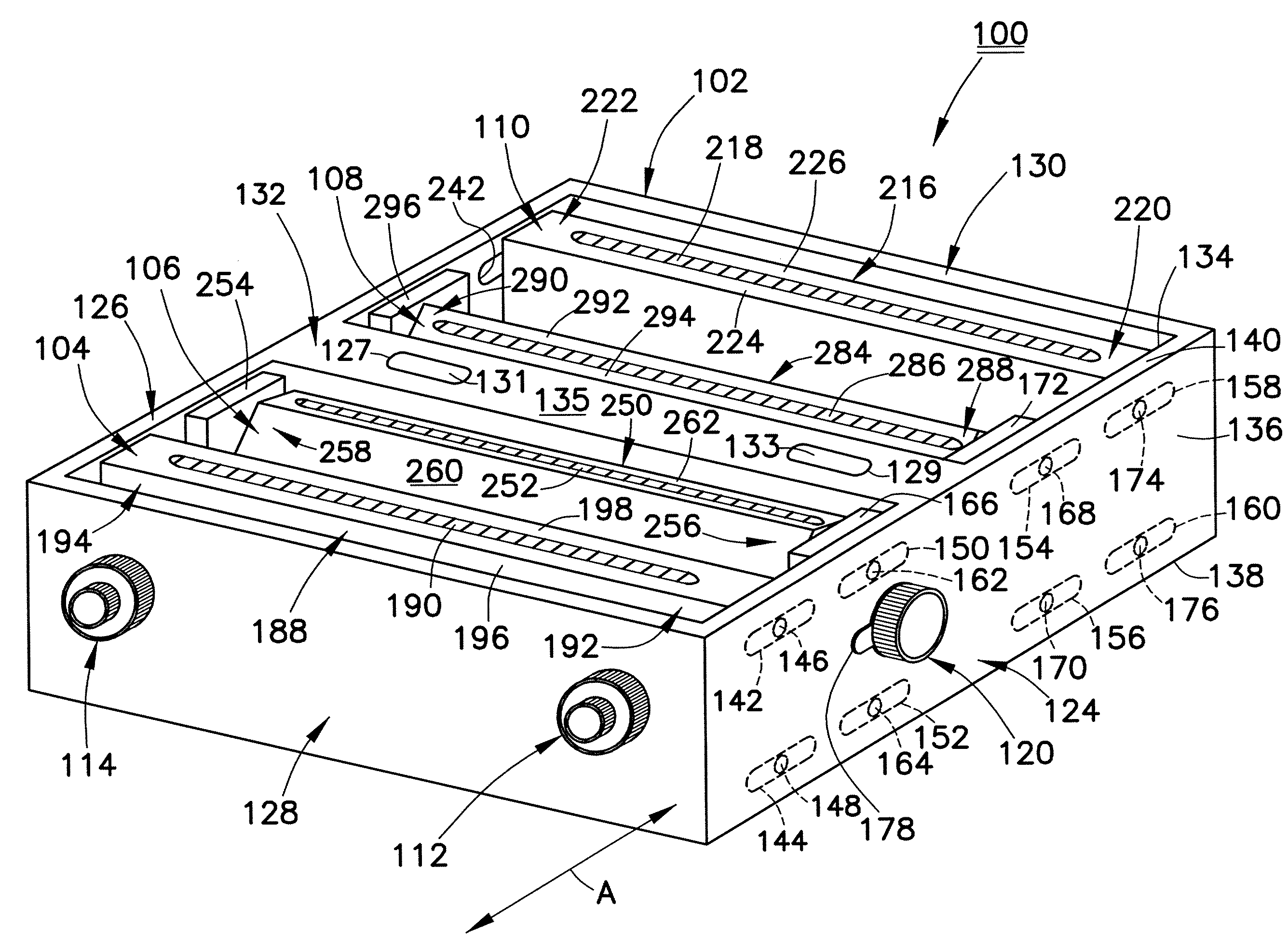
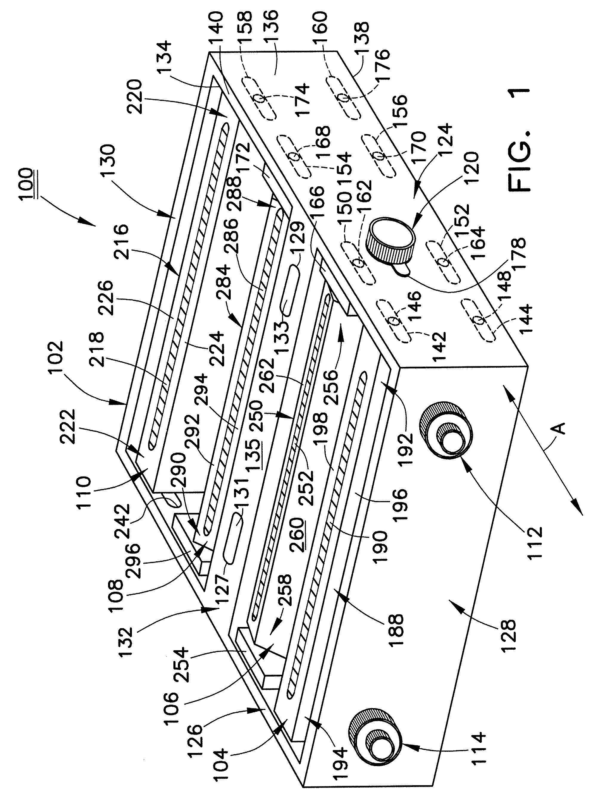
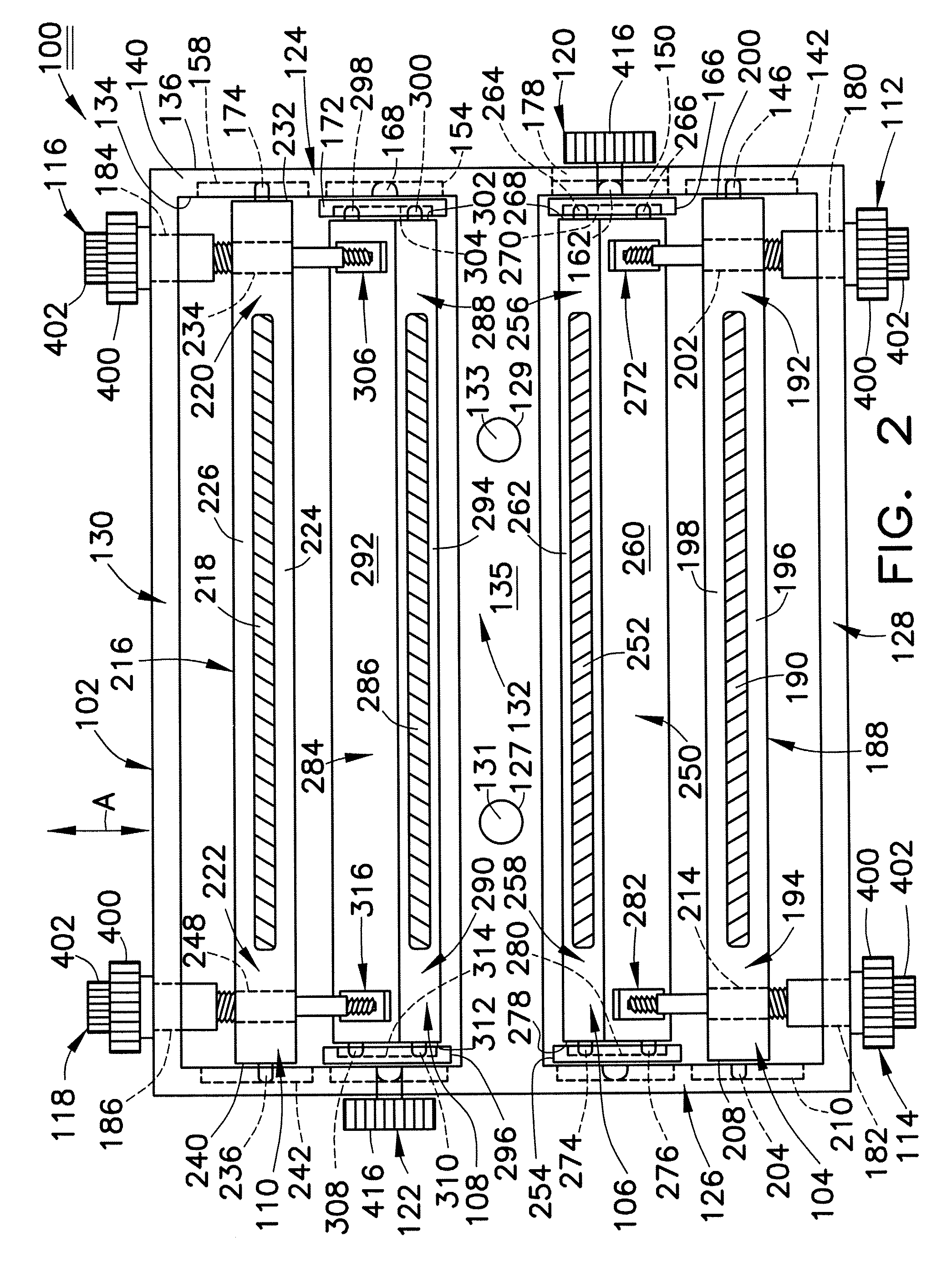
[0023]Referring now to FIGS. 1-3, one embodiment of a cutting block 100 for use in the present system is shown. Cutting block 100 generally includes a frame 102, four adjustable guides 104, 106, 108, 110, four linear adjustors 112, 114, 116, 118, and two angular adjustors 120, 122. It should be understood that the number of guides and adjustors may be different from the number described herein. More specifically, one skilled in the art could readily adapt the teachings of this disclo...


PUM


Abstract

A system for cutting a bone at a desired location may include an image guided drill cylinder configured to receive either a drill bit to create a bore at a target location on the bone or a pin for insertion into the target location, and a cutting block having a plurality of adjustable guides, each defining a cutting path to guide a cutting instrument, a mounting location configured to attach to the bone at the target location, and a plurality of adjustors for adjusting the position of the guides relative to the target location. The system may further include a tracking instrument for providing image guidance of the adjustments to the positions of the guides.

Description

FIELD OF THE INVENTION[0001]The present method, apparatus, and system generally relate to surgical removal of portions of bone, and more particularly to facilitating accurate location of a cutting path for guiding a cutting instrument when creating a cut through a portion of a bone.BACKGROUND AND SUMMARY OF THE INVENTION[0002]As a result of many different physiological conditions, it is often necessary to replace joints in various parts of the body with prosthetic components. Surgical procedures for preparing bones to receive such components typically require precise shaping of portions of the bones. For example, during knee joint replacement surgery, precise resection of the ends of the femur and tibia is necessary to achieve a very close match between the surfaces remaining after removal of portions of the bones, and the mating surfaces of the prostheses. Without such precision mating, the reconstructed knee may result in misalignment (alignment that differs from optimal alignment...

Claims


Application Information

Patent Timeline
Patent Type & Authority Patents(United States)
IPC IPC(8): A61B17/58A61B17/15A61B17/17A61B19/00
CPCA61B17/155A61B17/157A61B17/1703A61B17/1717A61B17/1725A61B34/20A61B17/1764A61B2090/3983A61B2034/102A61B2034/2055A61B2034/256A61B2034/107
Inventor LAKIN, RYAN CAMERONSHEFFER, GARRETTMCKALE, JIM
Owner BIOMET MFG CORP
Why Eureka
Try Eureka