Rotary electric machine and electric wheelchair mounted with rotary electric machine

a technology of rotary electric machines and electric wheelchairs, which is applied in the direction of electric devices, magnetic circuit rotating parts, magnetic circuit shapes/forms/construction, etc., can solve the problems of reducing the electric resistance at this fixed portion, the difficulty of firmly fixing the teeth, and energy loss, so as to reduce the working steps and ensure the accuracy of dimensional accuracy without reducing the electric resistance

Inactive Publication Date: 2010-01-05
YAMAHA MOTOR CO LTD
View PDF43 Cites 10 Cited by
  • Summary
  • Abstract
  • Description
  • Claims
  • Application Information

AI Technical Summary

Benefits of technology

[0015]The present invention was conceived in consideration of the above prior art, and an object of the present invention is to provide a rotary electric machine capable of fixing teeth at reduced working steps and ensuring dimensional accuracy without reducing electric resistance at the teeth fixing portion and also to provide an electric wheelchair mounted with such rotary electric machine.

Problems solved by technology

However, in such arrangement, because the molding resin 7 does not reach a portion surrounded by the bobbins 4, it was difficult to firmly fix the teeth 2.
However, in such conventional methods, when the tooth 2 is pushed into the fitting hole of the stator yoke core 6 and then fixed thereto or is welded to thereby increase contacting strength therebetween, there is a fear that an electric resistance at this fixed portion is reduced and a closed circuit is formed around the fitting hole in a plan view, resulting in energy loss due to large induction current flow.
In addition, in the method of using the punch, a fixing process using the punch will be additionally required, and moreover, the use of the punch will give an adverse impact, thus being troublesome and inconvenient for dimensional control.

Method used


Image

  • Rotary electric machine and electric wheelchair mounted with rotary electric machine
  • Rotary electric machine and electric wheelchair mounted with rotary electric machine
  • Rotary electric machine and electric wheelchair mounted with rotary electric machine

Examples


first embodiment

[0065]The first embodiment of the present invention is represented by FIGS. 1 to 11.

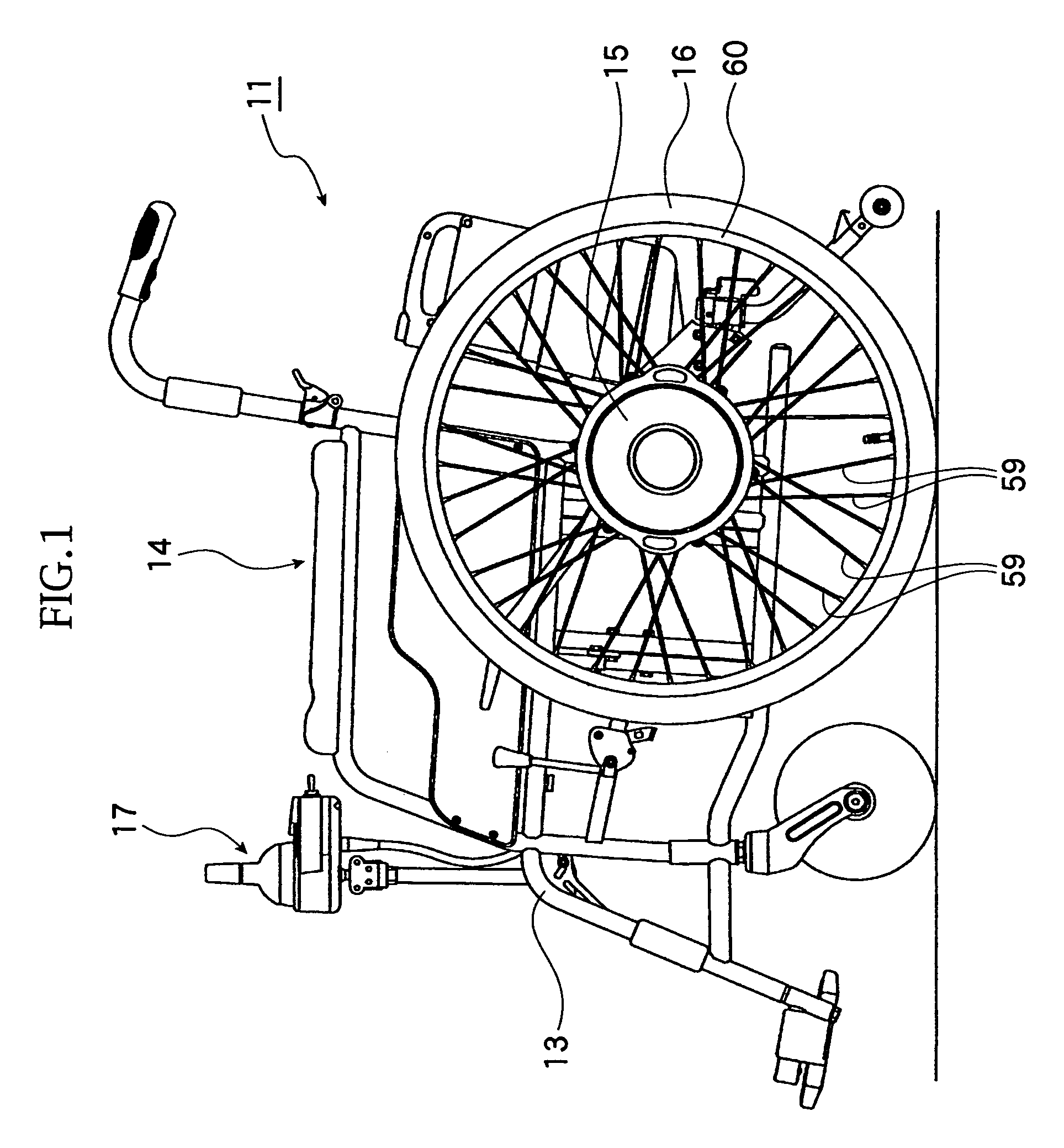
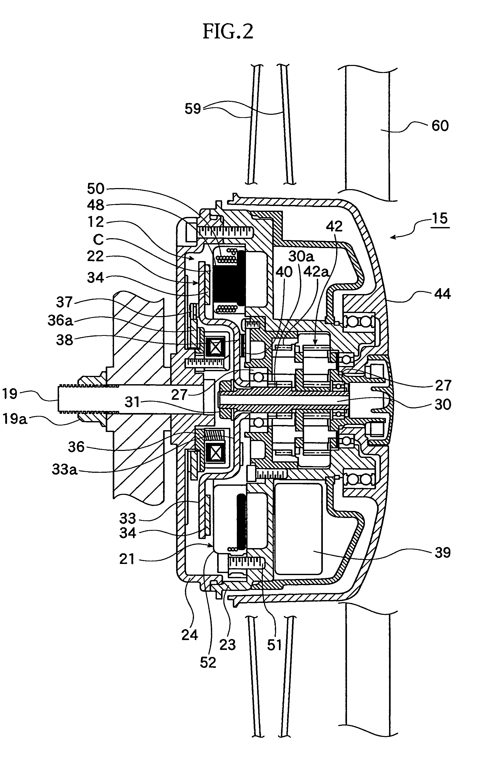
[0066]With reference to FIGS. 1 and 2, reference numeral 11 denotes an electric wheelchair or electrically powered wheelchair mounted with an electric motor 12 as a rotary electric machine according to the present invention, and the electric wheelchair is driven and traveled by the driving force of the electric motor 12.

[0067]The electric wheelchair 11 is provided with a frame 13 as a framework of a vehicle (electric wheelchair body), a seat 14 on which a user sits and a pair of driving wheel units 15 in which the electric motors 12 (see FIG. 2) are mounted. When an operation unit 17 of the electric wheelchair 11 is operated, the paired driving wheel units 15 are driven so as to drive driven wheels 16 by predetermined amount (distance). The driven wheels 16 are operated independently, and by operation of the operation unit 17, the driven wheels 16 are changed in their rotating directions and driven s...

second embodiment

[0095]FIG. 12 represents the second embodiment of the present invention.

[0096]In this second embodiment, the structure of the “coming-off preventing portion” differs from that of the first embodiment.

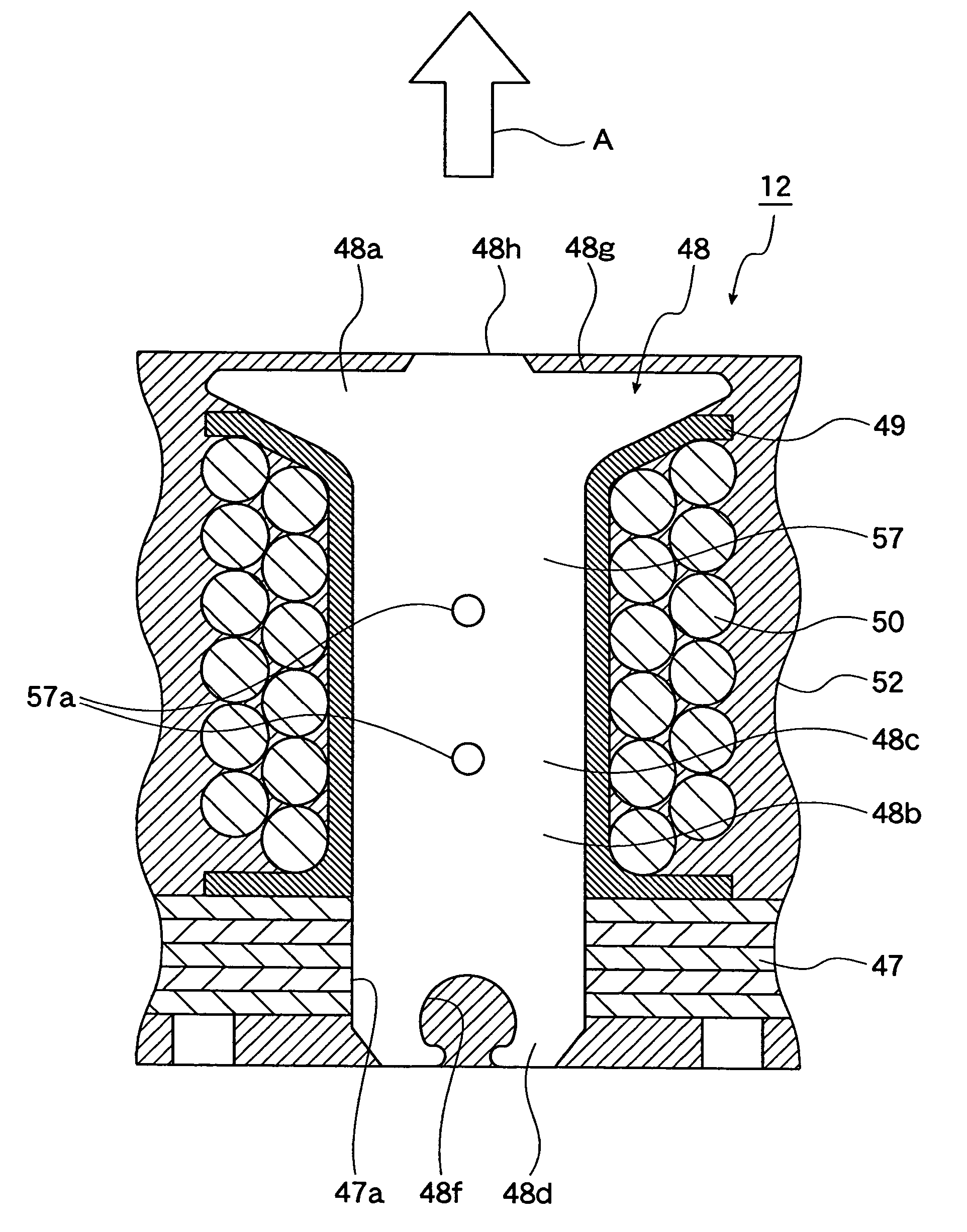
[0097]That is, in the first embodiment, the resin filling groove 48f as the “coming-off preventing portion” is formed on the end surface side of the end portion, which is a portion that penetrates the stator yoke core 47, of the insert portion 48d of the tooth 48, but in this second embodiment, a cut-out groove 48i as “coming-off preventing portion” is formed on the side surface side of the end portion, which is a portion that penetrates the stator yoke core 47, of the insert portion 48d of the tooth 48.

[0098]Even in this second embodiment having the above structure, the cut-out groove 48i is filled up with the molding resin 52, thus preventing the tooth 48 from coming off.

[0099]The structures and functions other than the above are substantially the same as those mentioned with referenc...

third embodiment

[0100]FIGS. 13 to 15 represent the third embodiment of the present invention.

[0101]In the first embodiment, a portion other than the protruded portion 48h of the tooth opposing surface 48a are covered entirely with the molding resin 52. However, in this third embodiment, the portion other than the protruded portion 48h is partially covered with the molding resin 52.

[0102]In this embodiment, at a time when the stator 21 is molded, the protruded portion 48h of the tooth opposing surface 48a is pressed by a pressing portion 63a of an upper half mold 63, as shown in FIG. 15, and the portion other than the protruded portion 48h is partially pressed by the other pressing portion 63b of the upper half mold 63.

[0103]Further, the stator yoke core 47 is positioned by abutting a positioning pin 64a formed to a lower half mold 64 against this stator yoke core 47.

[0104]As mentioned above, the tooth (teeth) 48 can be prevented from coming off by partially covering the portion other than the protr...


PUM


Abstract

A rotary electric machine includes a stator including a plurality of teeth, a coil wound around each tooth, and a stator yoke core that connects the respective teeth, the teeth and the stator yoke core integrally fixed by a molding resin. The rotary electric machine also includes a rotor with a plurality of magnets that face the teeth, the magnets and teeth separated from each other by a space therebetween. Each of the teeth comprises a head portion facing opposite the magnets, a coil wind-up portion around which the coil is wound up, and an insert portion that can be inserted into the stator yoke core, the insert portion including a groove formed in a portion of the insert portion that protrudes from the stator yoke core, where the groove is fillable with the molding resin to inhibit the teeth from disengaging from the stator yoke core.

Description

CROSS-REFERENCE TO RELATED APPLICATIONS[0001]This application claims the priority benefit of Japanese Patent Application No. 2005-210498, which was filed on Jul. 20, 2005.BACKGROUND OF THE INVENTION[0002]1. Field of the Invention[0003]The present invention relates to a rotary electric machine having an improved fixing structure for teeth of a stator of the rotary electric machine, and also relates to an electric wheelchair (or electrically powered wheelchair) mounted with such rotary electric machine.[0004]2. Related Art[0005]In a known art, as such a rotary electric machine, there has been provided an axial gap type rotary electric machine as shown, for example, in FIGS. 16 to 19.[0006]Referring to FIGS. 16 to 19, the rotary electric machine is provided with a stator 3 formed with teeth 2 and a rotor provided with a plurality of magnets (permanent magnets), not shown, in which the stator and the rotor are arranged with a gap in a rotation axis direction.[0007]More in detail, as sho...

Claims


Application Information

Patent Timeline
Patent Type & Authority Patents(United States)
IPC IPC(8): H02K1/18A61G5/04H02K21/24
CPCH02K1/148H02K5/08H02K7/14B60L2220/44B60L2200/34Y02T10/64
Inventor NAITOU, SHINYAHINO, HARUYOSHI
Owner YAMAHA MOTOR CO LTD
Why Eureka
Try Eureka