
Portable instrument for measuring a physiological quantity, including a device for illuminating the surface of an organic tissue

Active Publication Date: 2010-01-05
THE SWATCH GRP RES & DEVELONMENT LTD
View PDF20 Cites 7 Cited by
  • Summary
  • Abstract
  • Description
  • Claims
  • Application Information

AI Technical Summary

Benefits of technology

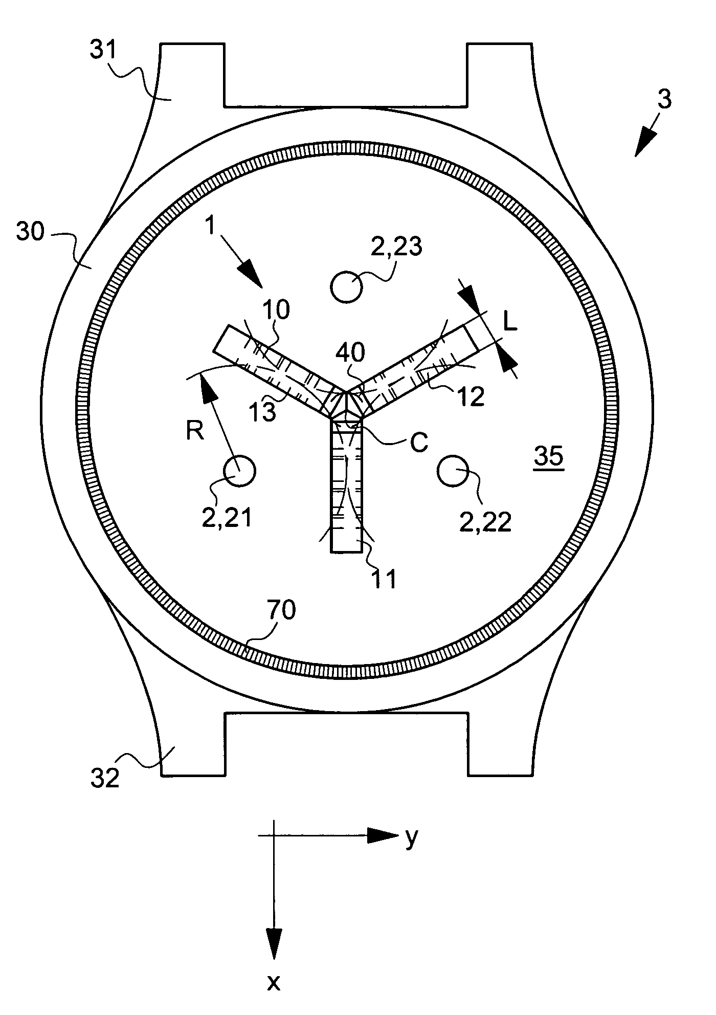
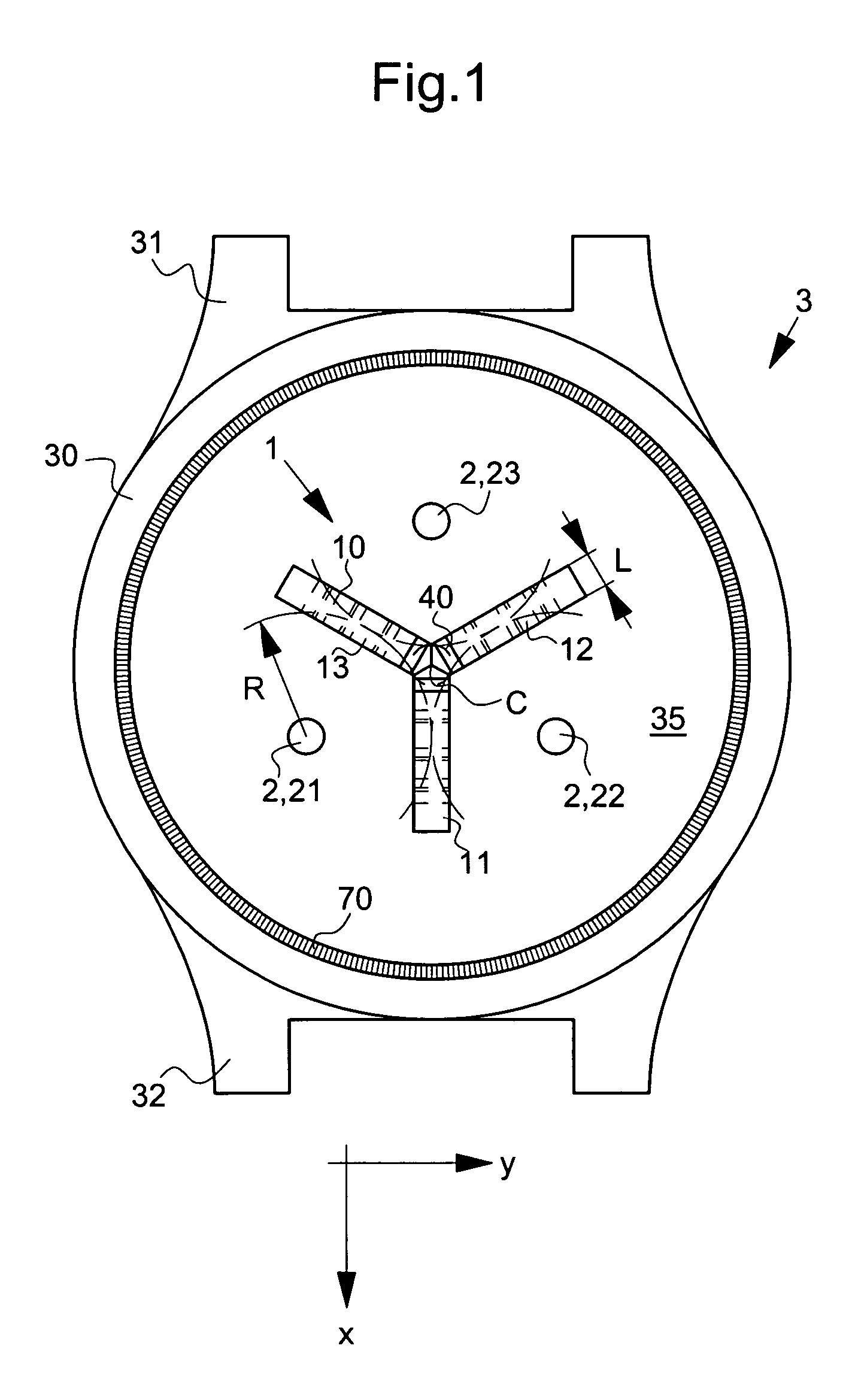
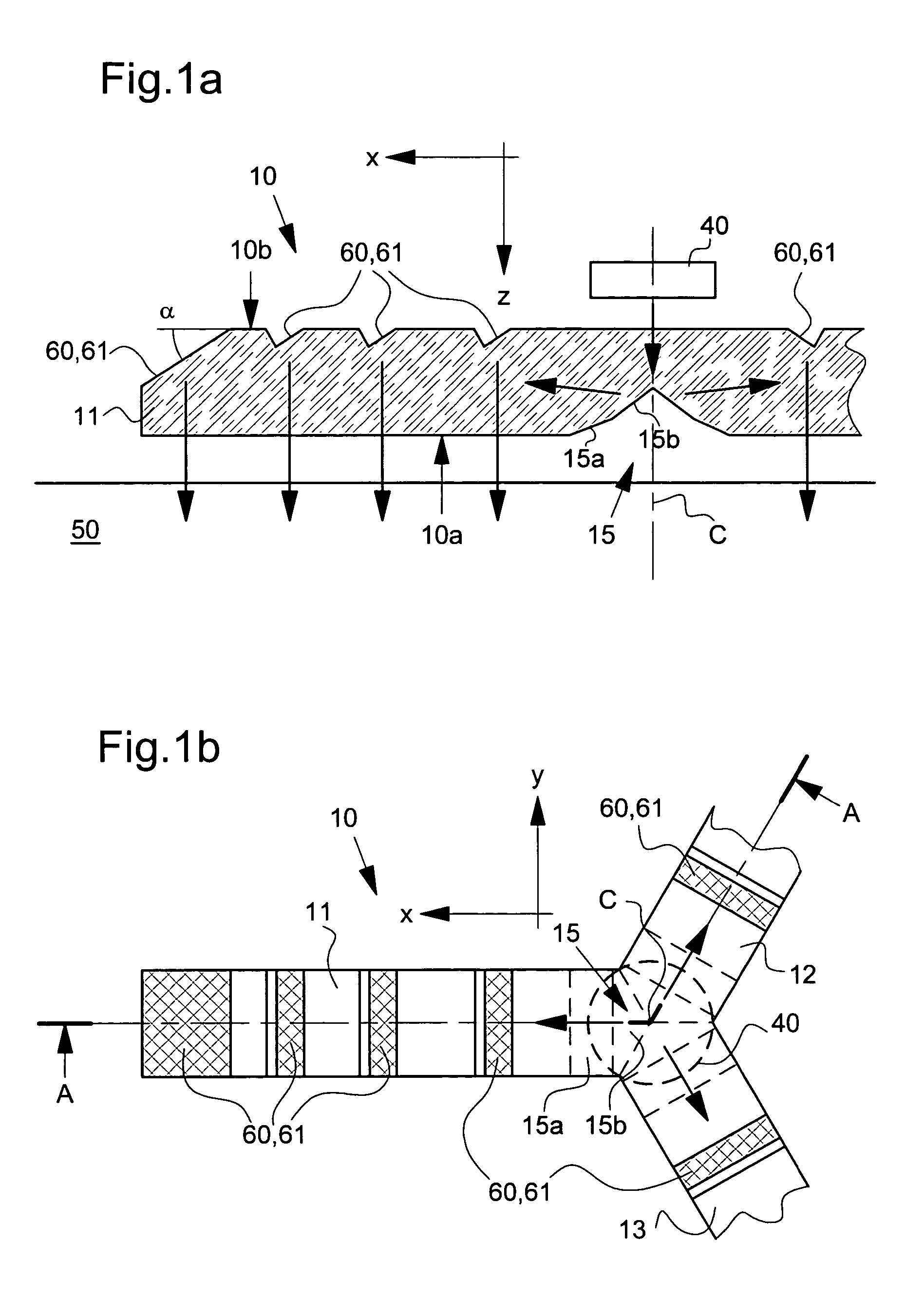
[0017]This solution optimises as far as possible the space available to assure adequate illumination of the organic tissue. The inventor was able to observe in fact that an optical element thus structured was particularly well suited to generating the required illumination assuring optimal detection of the desired physiological quantity. This solution allows the light flux produced by the light source or sources to be channeled in a successful and optimum manner in order to illuminate the organic tissue in a number of zones arranged in a determined manner in proximity to the detection device. This solution further favours optimisation of illumination for a given energy consumption. According to the solutions of the prior art, the light flux from the light sources is not, so to speak, channeled. This results in non-optimal illumination, not only in terms of distribution, but also in terms of energy consumption, since the light emission is propagated in any direction around the source. According to the present solution, the optical element can be structured such that the light emission emerging from the optical element illuminates the organic tissue at a predetermined angle in the direction of the detection device, thus optimising still further the use of the available energy.
[0018]It will be noted in particular, that the optical illumination guide can be structured so as to assure that the light emission emanating from the illumination device is close to a vertical line relative the organic tissue to be illuminated. This advantageously enables the organic tissue to be illuminated in depth while avoiding insofar as possible direct coupling between the illumination and detection devices. According to the solutions of the prior art, the drawback of the conventional light sources (particularly LEDs) lies in the non-oriented nature of the light emission generated, the light emission thus being propagated in all directions in the organic tissue. The use of an optical guide for illuminating the organic tissue enables the light emission to be channeled so that it is propagated in depth in the tissue. The use of an optical guide for detection likewise favours detection of the light emission originating from the depths of the illuminated organic tissue, to the detriment of any light emission which is propagated at the surface of the organic tissue and which is only slightly modulated by the blood flow.
[0020]In order to assure illumination or detection that is as uniform and homogenous as possible, the length of the micro-prismatic structures and / or their number preferably increases progressively as one moves away from the light source, respectively from the associated photoreceptor, along the optical path of the light emission. These two alternatives are applicable independently of each other or in combination and have the advantage of compensating for the decrease in intensity of the light emission produced or picked up.
[0022]The first facet at least of each micro-prismatic structure can be coated with a reflective coating in order to increase the useful light flux for illumination or detection. More widespread parts of the walls of the optical element, such as the lateral walls or the upper wall of the optical element, could be coated with a reflective coating. It should be noted that by totally coating the surface where the micro-prismatic structures are arranged, the manufacturing cost premium can be reduced a little with respect to a selective coating of the micro-prismatic structures alone, but absorption losses due to the reflective surfaces are also increased.
[0025]Finally, the aforementioned portable measuring instrument is perfectly suited for use in an electronic instrument worn on the wrist. The solution proposed is particularly advantageous since the optical element of the illumination device has a relatively simple construction and a small thickness allowing it to be incorporated in the bottom of the case of the instrument in proximity to the user's skin.

Problems solved by technology

Alternatively, it is further proposed to dispose several light emitting diodes around a single photoreceptor, this alternative however being undesirable because of the increase in energy consumption and the proportional increase in manufacturing and construction costs.
This reduced emitting or illumination surface has a drawback for applications requiring illumination of an organic tissue insofar as the organic tissue has so to speak systematically localised zones where the degree of light emission absorption differs greatly from neighbouring zones.
In the case of illumination of a user's skin for example, moles, hairs or other localised modifications in the epidermis can thus cause a significant variation in the light emission absorption and have a negative influence on the quality of measurement of the desired physiological quantity.
Any relative movements between the measuring device and the illuminated organic tissue further add to the degradation of the measurement quality.
It will be understood that these problems also arise in relation to the detection device.
As already mentioned with reference to US document No. 2002 / 0188210 A1 hereinbefore, this solution is not, however essentially desirable for reasons of energy consumption and costs.
It should however be noted that the increase in the number of light sources also generates connection and construction problems.

Method used


Image

  • Portable instrument for measuring a physiological quantity, including a device for illuminating the surface of an organic tissue
  • Portable instrument for measuring a physiological quantity, including a device for illuminating the surface of an organic tissue
  • Portable instrument for measuring a physiological quantity, including a device for illuminating the surface of an organic tissue

Examples


Embodiment Construction

[0037]The various embodiments that will now be presented are given purely by way of illustrative and non-limiting example. In particular, it should again be stressed that the embodiments that will be presented can advantageously but not uniquely be implemented in an instrument intended to be worn on the wrist. Other portable applications of these solutions may perfectly well be envisaged.

[0038]In the embodiments illustrated in the Figures, it will be noted that a common point lies in the use of an illumination device including at least one light source coupled to a structured optical element forming a guide, this guide being structured in a determined manner as a function of geometry (in particular its periphery) and the arrangement of the detection device. As will be seen hereinafter, the detection device can also be provided with at least one optical element forming a guide coupled to at least one photoreceptor. By way of alternative, one could envisage, within the scope of the in...


PUM


Abstract

A portable instrument for measuring a physiological quantity arranged to contact with the surface of organic tissue includes, essentially arranged in the same plane: an illumination device including at least one light source with an illumination surface for subjecting a portion of organic tissue to light emission in at least one wavelength range; and a detection device distant from the illumination device for detecting intensity of light emission produced by the illumination device after propagation in the organic tissue. The illumination device includes an optical element forming a guide coupled to the at least one light source for guiding light emission from the source by total internal reflection in a substantially parallel direction to the surface of the organic tissue and for distributing light emission into several illumination zones on the surface of the organic tissue over a substantially broader area than the illumination surface of the light source.

Description

[0001]This application claims priority from Swiss Patent Application No. 0904 / 03 filed May 21, 2003, the entire disclosure of which is incorporated herein by reference.FIELD OF THE INVENTION[0002]The present invention concerns in general a portable instrument for measuring a physiological quantity (for example the heart rhythm) arranged to be brought into contact with the surface of an organic tissue (for example skin) including, essentially disposed in a same plane, an illumination device including at least one light source of a determined illumination surface for subjecting a portion of the organic tissue to a luminous emission in at least one determined wavelength range, and a detection device remote from the illumination device for detecting the intensity of the luminous emission produced by the illumination device after propagation in the organic tissue. The present invention concerns more particularly such a measurement instrument capable of being worn on the wrist, for exampl...

Claims


Application Information

Patent Timeline
IPC IPC(8): A61B5/1455A61B5/00G01N21/35A61B5/024A61B5/0245A61B5/145
CPCA61B5/02416A61B5/02438A61B5/681A61B5/00
Inventor GUEISSAZ, FRANCOIS
Owner THE SWATCH GRP RES & DEVELONMENT LTD
Learn More