Sound attenuator

a sound attenuator and sound technology, applied in the field of ducts, can solve the problems of reducing the operational efficiency of the duct, noise, sedimentation of suspended solids, and reducing efficiency, so as to facilitate a change of direction and reduce the turbulence of fluid flow

Inactive Publication Date: 2010-01-12
PAX SCI +1
View PDF159 Cites 13 Cited by
  • Summary
  • Abstract
  • Description
  • Claims
  • Application Information

AI Technical Summary

Benefits of technology

[0010]In a first claimed embodiment of the present invention, a duct disclosed that may be configured to facilitate a change of direction in the flow of a fluid. The duct includes an inlet and an outlet for receiving and expelling fluid, respectively. The inlet corresponds to a first direction of fluid flow whereas the outlet concerns a second direction that differs from the direction of the inlet. An intermediate pathway is situated between the inlet and outlet. The pathway excludes a substantially right angle bend but includes a curvature that induces a vortical flow that reduces turbulence in fluid flow as a fluid traverses the pathway.
[0011]In a second claimed embodiment, a duct is provided and that may be configured to facilitate flow of a fluid. The duct includes an inlet, outlet, and intermediate pathway. A portion of the intermediate fluid pathway includes a spiral twist that induces a spiral flow that reduces turbulence as the fluid traverse the intermediate pathway.
[0012]A further claimed embodiment of the present invention is for a cardiovascular stent that reduces fatty deposits when disposed in a blood flow pathway. The stent includes an inlet, outlet, and intermediate fluid pathway. A portion of the intermediate fluid pathway includes a helical twist that induces a spiral flow that, in turn, reduces turbulence thereby inhibiting the formation of fatty deposits as blood traverses the blood flow pathway.
[0013]A fourth claimed embodiment of the present invention is for a fluid flow controller that reduces turbulence in fluid flow. The controller includes an inlet for receiving the fluid, an outlet for expelling the fluid, and an intermediate fluid pathway between the inlet and the outlet. The intermediate fluid pathway conforms substantially to the form of a shell configuration from the phylum Mollusca, class Gastropoda, genus Volutidae. The shell configuration of the intermediate fluid pathway induces a spiral flow that reduces turbulence in the fluid flow.

Problems solved by technology

The principal difficulty with previous arrangements however, has been turbulence created within the fluid flow which reduces efficiency.
In extreme circumstances, in the case of liquids, the turbulence can result in cavitation, which not only reduces the operational efficiency of the duct but can result in inefficiencies, noise, heating, sedimentation of suspended solids, accelerated electrolysis or corrosion through oxygenation of the fluid, and destructive influences upon the structure of the duct.
In cardiovascular devices such as straight-sided stents, deleterious cavitation and / or plaque deposits can occur.
This can result in significant inefficiencies.

Method used


Image

  • Sound attenuator
  • Sound attenuator
  • Sound attenuator

Examples


first embodiment

[0037]A first embodiment shown in FIG. 3 and FIG. 4 relates to a duct section which facilitates the change in direction of fluid or fluid pathways within plumbing or ducting systems such as water pipes or air conditioning systems.

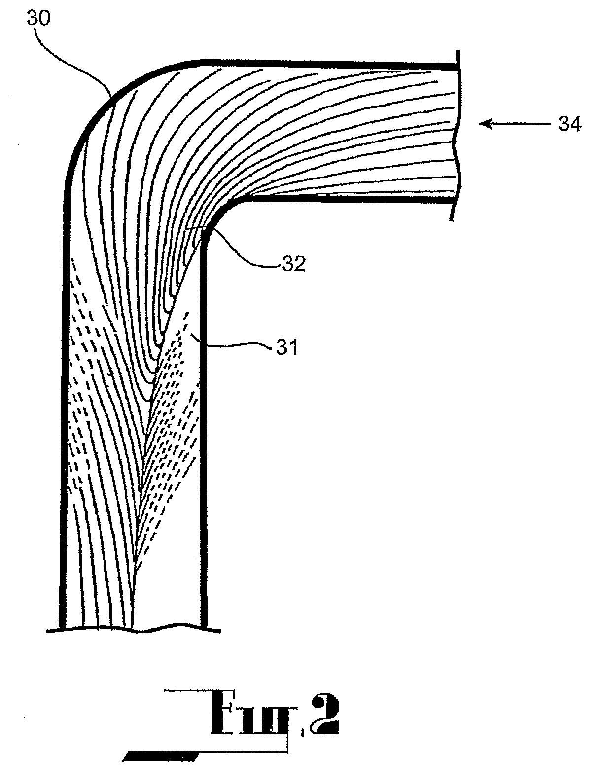
[0038]As can be seen in FIG. 2, a conventional right angle bend (30) in pipe or ducting results in fluid flow that is less than optimal. Streamlines show a low-pressure area (31) and a high-pressure area (32). This can result in turbulence, cavitation, sedimentation and corrosion as well as increasing energy losses in the fluid movement (34). This can result in increased pumping costs and reduced pressure at the outlet.

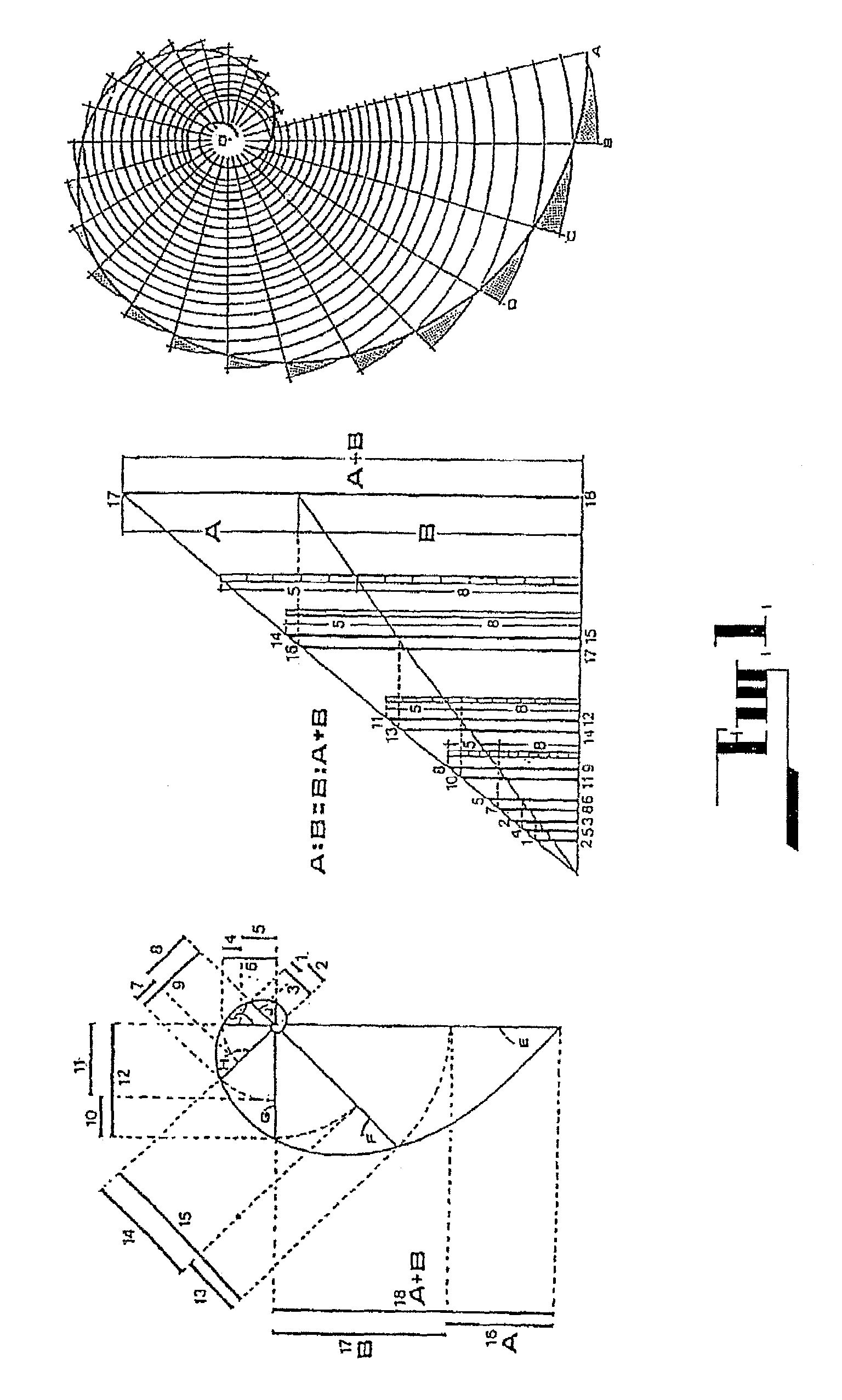
[0039]This form of the embodiment shown in FIGS. 3 and 4 provides a duct (36) specifically designed to induce the fluid (34) to move in accordance with the laws of Nature whilst changing its direction. As mentioned previously, the duct is designed having a pathway having a curvature (37) substantially or in greater part conforming to that of ...

second embodiment

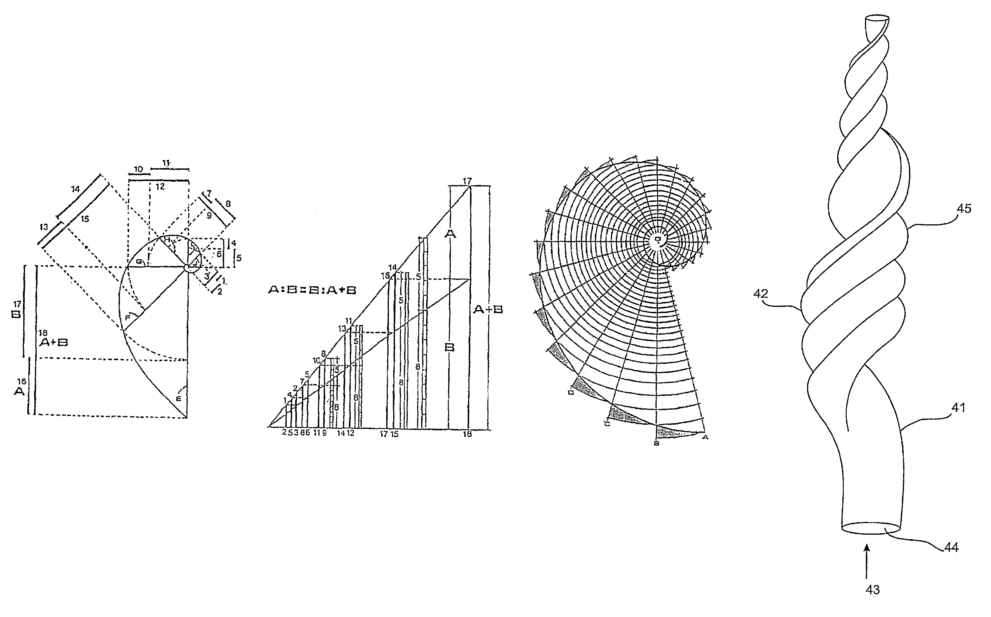
[0041]A second embodiment shown in FIGS. 5 and 6 relates to a duct (41) providing a twisting pathway (42) for fluids where the pathway conforms to the Golden Section or Ratio. As fluid (43) flows through the inside (44) of the duct, it is urged to conform to natural flow spiral characteristics, which minimize extraneous turbulence.

[0042]In an adaptation of the second embodiment, there is provided a flow controller having the form as shown in FIG. 5 and 6, the flow controller adapted to be located within a fluid pathway. In this form the flow of the fluid is around the outside of the flow controller. It is therefore the external surface of the flow controller which is active and is designed to conform to the Golden Section. However, in this adaptation, the flow controller may be hollow which allows the fluid to flow through it internally.

third embodiment

[0043]A third embodiment shown in FIG. 7 depicts a duct (51) providing a twisting pathway (52) for fluids conforming to the Golden Section or Ratio. As fluid (53) flows through the inside or outside of the duct it is urged to conform to natural flow spiral characteristics, which minimize extraneous turbulence. Additionally, the diagram shows the fluid's spiralling flow path on the fluid as it flows.

[0044]An example of a duct constructed in accordance with the third embodiment is a cardiovascular stent. Conventionally, stents have been cylindrical in shape. While intended to be permanently placed within the patient, it has been found in many cases, that fatty deposits are formed within the stent over a period of time, requiring their replacement. It is believed that this build up is caused as a result of the turbulence in the stent. A stent constructed in accordance with the third embodiment will avoid this turbulent flow and thereby prevent the formation of fatty deposits in the ste...


PUM


Abstract

A fluid pathway is provided with a flow controller in at least a portion of its length wherein the flow controller comprises an active surface capable of influencing the fluid flow through the fluid pathway, the configuration of the active surface conforming to at least one logarithmic curve conforming to the Golden Section.

Description

CROSS REFERENCES TO RELATED APPLICATIONS[0001]This application is a continuation and claims the priority benefit of U.S. patent application Ser. No. 10 / 882,412 filed Jun. 30, 2004 and entitled “Fluid Flow Controller,” which is a continuation and claims the priority benefit of Patent Cooperation Treaty application number PCT / AU03 / 00004 filed Jan. 3, 2003, which in turn claims the priority benefit of Australian patent application number PR 9823 filed Jan. 3, 2002. The disclosure of the aforementioned applications is incorporated herein by reference.[0002]The present application is related to U.S. patent application Ser. No. 11 / 323,137 filed Dec. 29, 2005 and entitled “Fluid Flow Control Device.”FIELD OF THE INVENTION[0003]The present invention relates to ducts adapted to convey a fluid. Examples of the particular applications of the invention include plumbing systems, air-conditioning ducts, cardiovascular stents, dust precipitators, sound attenuators, mufflers and chambers, exhaust p...

Claims


Application Information

Patent Timeline
Patent Type & Authority Patents(United States)
IPC IPC(8): F01N1/12F15C1/16F01N1/08A61F2/00A61F2/06A61F2/82F15D1/02F15D1/04F16L55/02F16L55/027
CPCF01N1/12F15D1/02F16L55/02772F15C1/16F15D1/04A61F2/82A61F2002/068A61F2002/30296A61F2230/0091Y10T137/2098F25D25/025Y10T137/2087Y10T137/2104A61F2002/30291F16L55/02F16L55/045F16L55/027F16L55/04
Inventor HARMAN, JAYDEN DAVID
Owner PAX SCI
Why Eureka
Try Eureka