Gas-measuring system with gas sensor and gas generator

a gas sensor and gas generator technology, applied in the direction of gas analyser calibration, material thermal analysis, sonic/ultrasonic/infrasonic wave analysis of fluids, etc., can solve the problem of high cost of carrying out function tests and calibration procedures, gas sensors have drift in sensitivity of sensors with respect to species to be detected, and safety-relevant risks. , to achieve the effect of stable operation and minimal fault susceptibility to environmental effects

Active Publication Date: 2010-01-12
DRAGER SAFETY
View PDF15 Cites 27 Cited by
  • Summary
  • Abstract
  • Description
  • Claims
  • Application Information

AI Technical Summary

Benefits of technology

[0014]An essential advantage of the present invention is that the test gas does not have to be delivered actively to the sensor and the device has minimal fault susceptibility to environmental effects due to the proximity in space of the gas generator and the detector. The fact that the measuring surface and the discharge surface are arranged adjacent to one another makes it possible to admit very small quantities of target gas to the gas sensor. It was found that especially if the above-described advantageous symmetry condition is complied with, a configuration is obtained that is characterized by a surprisingly stable operation and even permits undisturbed and reliable operation under extreme external air flows.
[0015]The gas sensor and the gas generator may be designed according to the present invention as separate assembly units capable of operating independently from one another. The designs of the assembly units are of secondary importance. However, these units must be designed such that the closely spaced arrangement according to the present invention of the measuring surface of the gas generator and the discharge surface of the gas generator is possible for testing and calibration purposes. Arrangements in which the distance according to the present invention is maintained and there are no flow obstacles in the direct path between the measuring surface and the discharge surface are considered to be closely adjacent to one another. It proved to be especially advantageous if the two surfaces are exposed to the same flow conditions during testing and / or calibration. This is achieved, for example, by a radially symmetrical arrangement, in which the measuring surface and the discharge surface are located in one plane. The measuring surface may surround the discharge surface either radially symmetrically or vice versa.
[0016]The present invention will be explained on the basis of two exemplary embodiments. The various features of novelty which characterize the invention are pointed out with particularity in the claims annexed to and forming a part of this disclosure. For a better understanding of the invention, its operating advantages and specific objects attained by its uses, reference is made to the accompanying drawings and descriptive matter in which preferred embodiments of the invention are illustrated.

Problems solved by technology

First, an undiagnosed failure of a gas sensor, e.g., due to blockage of the entry of gas or inactivation of the detector element, may lead to safety-relevant risks in an area being monitored.
Second, commercially available gas sensors have a drift in the sensitivity of the sensor with respect to the species to be detected.
The expense of carrying out these function tests and calibration procedures is high.
Occasional activation of the gas generator thus makes it possible to test the sensor function, but it fails to provide information on the state of the transport paths via which the target gas enters during regular measuring operation.
It is difficult to infer the state of the outer membrane granting access for the gas to the detector electrode in this case as well.
However, the entry of gas from the outside to this chamber and consequently also to the detector electrode of the sensor continues to be untested in this design as well.
These methods also have the drawback that the path of the ambient gases to the detector electrode is not tested under realistic conditions.

Method used


Image

  • Gas-measuring system with gas sensor and gas generator
  • Gas-measuring system with gas sensor and gas generator
  • Gas-measuring system with gas sensor and gas generator

Examples


Embodiment Construction

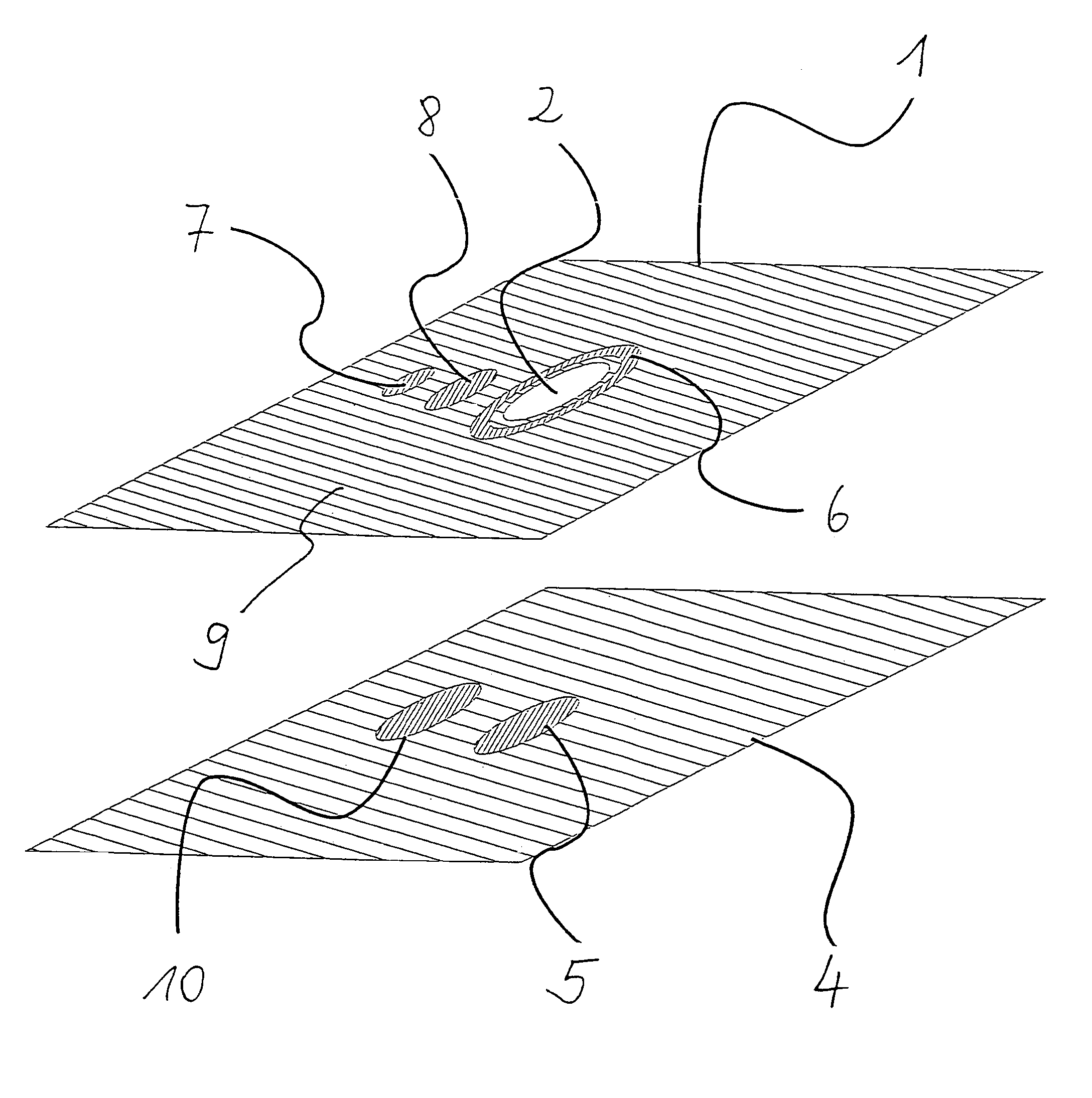
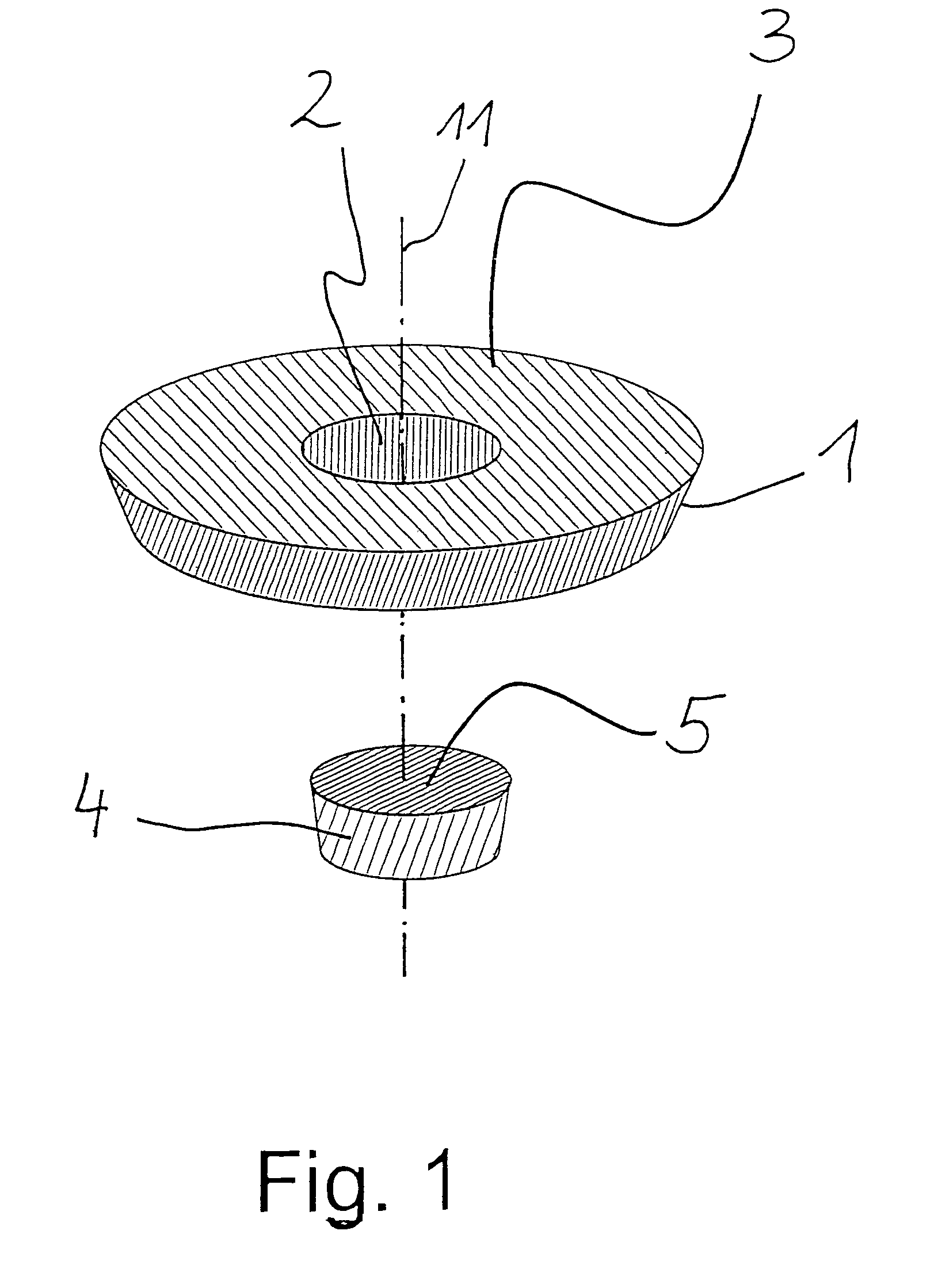
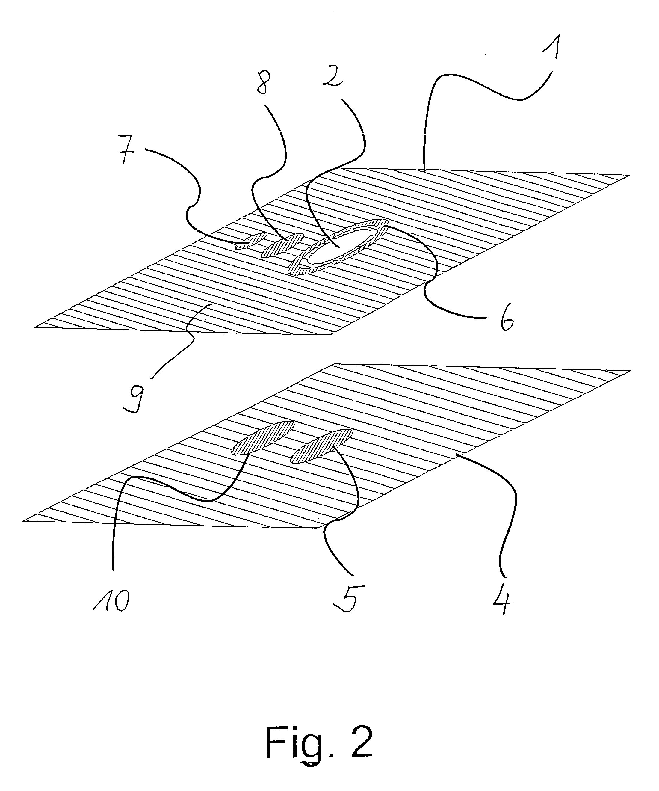
[0020]Referring to the drawings in particular, FIG. 1 shows a gas-measuring system according to the present invention. It comprises as the gas sensor 1 an electrochemical three-electrode sensor, as it can be used to detect hydrogen sulfide. The sensor contains a working electrode consisting of iridium, an auxiliary electrode consisting of platinum, and a platinum / platinum oxide reference electrode. Sulfuric acid is used as the electrolyte. The housing of the sensor has the shape of a flat truncated cone and has an opening 2 in the center. The base is closed with a gas-permeable membrane and acts in the sense of the present invention as a measuring surface 3, at which a target gas concentration can be measured. The gas-measuring system according to the present invention comprises, furthermore, a tablet-shaped hydrogen sulfide generator as the gas generator. A base of the generator acts as a discharge surface 5 in the sense of the present invention, from which a quantity of hydrogen s...


PUM

PropertyMeasurementUnit
concentrationaaaaaaaaaa
areaaaaaaaaaaa
timeaaaaaaaaaa

Abstract

A gas-measuring system contains at least one gas sensor (1) and at least one gas generator (4). The gas sensor (1) has at least one measuring surface (3), at which a target gas concentration can be measured. The gas generator (4) has at least one discharge surface (5), from which a current-proportional quantity of test gas can be discharged. The measuring surface (3) and the discharge surface (5) are designed and the gas sensor (1) and the gas generator (4) can be arranged such that the measuring surface (3) and the discharge surface (5) are in direct contact with the ambient atmosphere and the distance between the two surfaces is shorter than the extension of the smaller of the two surfaces.

Description

CROSS REFERENCE TO RELATED APPLICATIONS[0001]This application claims the benefit of priority under 35 U.S.C. § 119 of German Patent Application 10 2005 017 445.0 filed Apr. 15, 2005, the entire contents of which are incorporated herein by reference.FIELD OF THE INVENTION[0002]The present invention pertains to a gas-measuring system with a gas sensor and a gas generator. Such systems can be used advantageously wherever the readiness of gas-measuring systems to operate must be guaranteed over a rather long time. This applies, for example, to the use of permanently installed gas warning means or mobile gas-measuring systems that are in use for a rather long time.BACKGROUND OF THE INVENTION[0003]In case of the use of gas warning means, it is necessary essentially for two reasons to let the gas sensors used respond in a specific manner. First, an undiagnosed failure of a gas sensor, e.g., due to blockage of the entry of gas or inactivation of the detector element, may lead to safety-rele...

Claims


Application Information

Patent Timeline
Patent Type & Authority Patents(United States)
IPC IPC(8): G01N27/26G01N27/404
CPCG01N33/0006G01N27/4163G01N27/4175
Inventor TSCHUNCKY, PETERKIESELE, HERBERTKUHN, UWEMETT, FRANKHENGSTENBERG, ANDREASCARO, KERSTIN
Owner DRAGER SAFETY
Why Eureka
Try Eureka