Low cost dynamic insulated glazing unit

a technology of dynamic insulation and low cost, which is applied in the direction of optical radiation measurement, building repair, instruments, etc., can solve the problems of increasing the cost of operating the building, increasing the consumption of petroleum products and other non-recoverable resources, and wasting large amounts of energy, so as to reduce the intensity of radiation and control the radiation transmittance

Active Publication Date: 2010-01-12
GUARDIAN GLASS LLC
View PDF21 Cites 78 Cited by
  • Summary
  • Abstract
  • Description
  • Claims
  • Application Information

AI Technical Summary

Benefits of technology

[0008]According to an aspect of the invention, an insulated glazing unit has controllable radiation transmittance. A first glazing pane is attached at its periphery to a second glazing pane with a spacer separating them, the resultant assembly being attached at its periphery to a supporting structure. The first glazing pane and the second glazing pane are arranged such that an inner surface of the first glazing pane and an inner surface of the second glazing pane face each other and are spaced apart from each other. A conductive layer is disposed atop the inner surface of the first glazing pane and forms a fixed position electrode. A dielectric layer is disposed atop the conductive layer. A variable position electrode is disposed between the first glazing pane and the second glazing pane and is configured as a coiled spiral roll. An outer edge of the coiled spiral roll is attached along a width thereof to the dielectric layer. The variable position electrode includes a resilient layer and a further conductive layer. A first electrical lead is connected to the conductive layer of the variable position electrode, and a second electrical lead is connected to the conductive layer atop the inner surface of the first glazing pane. When a voltage is applied between the first electrical lead and the second electrical lead and creates a predetermined potential difference between the fixed position electrode and the variable position electrode, the variable position electrode unwinds and rolls out to cover at least part of the first glazing pane and thereby at least reduces the intensity of radiation passing through the insulated glazing unit.

Problems solved by technology

Glass windows, skylights, doors, and the like which are used in buildings and other structures are known to waste large amounts of energy.
The windows permit the infrared radiation of sunlight to pass into the interior of the building and cause unwanted heating, particularly during summer months, thus requiring increased use of air conditioning to remove the unwanted heat.
The increased use of air conditioning and heating increases the costs of operating the building and causes increased consumption of petroleum products and other non-recoverable resources.
The increased consumption of these resources has become particularly critical as, for example, supplies of petroleum decrease and the price of petroleum rises.
Also, at the same time that this increased consumption has become critical, new constructions of residential and commercial structures incorporate more glass than was used in older constructions, thereby further increasing consumption of these non-recoverable resources.
Unfortunately, the use of tinted Low E glass also requires a significant and undesirable trade-off between its optical clarity and its effectiveness in reducing the passage of heat and radiation through the tinted Low E glass.
Undesirably, IG windows that incorporate functional electronic layers are difficult and costly to manufacture, have a questionable operating life, have undesirable operating temperatures, have very slow response times, provide incomplete darkening, and increase power consumption by their operation.

Method used


Image

  • Low cost dynamic insulated glazing unit
  • Low cost dynamic insulated glazing unit
  • Low cost dynamic insulated glazing unit

Examples


Embodiment Construction

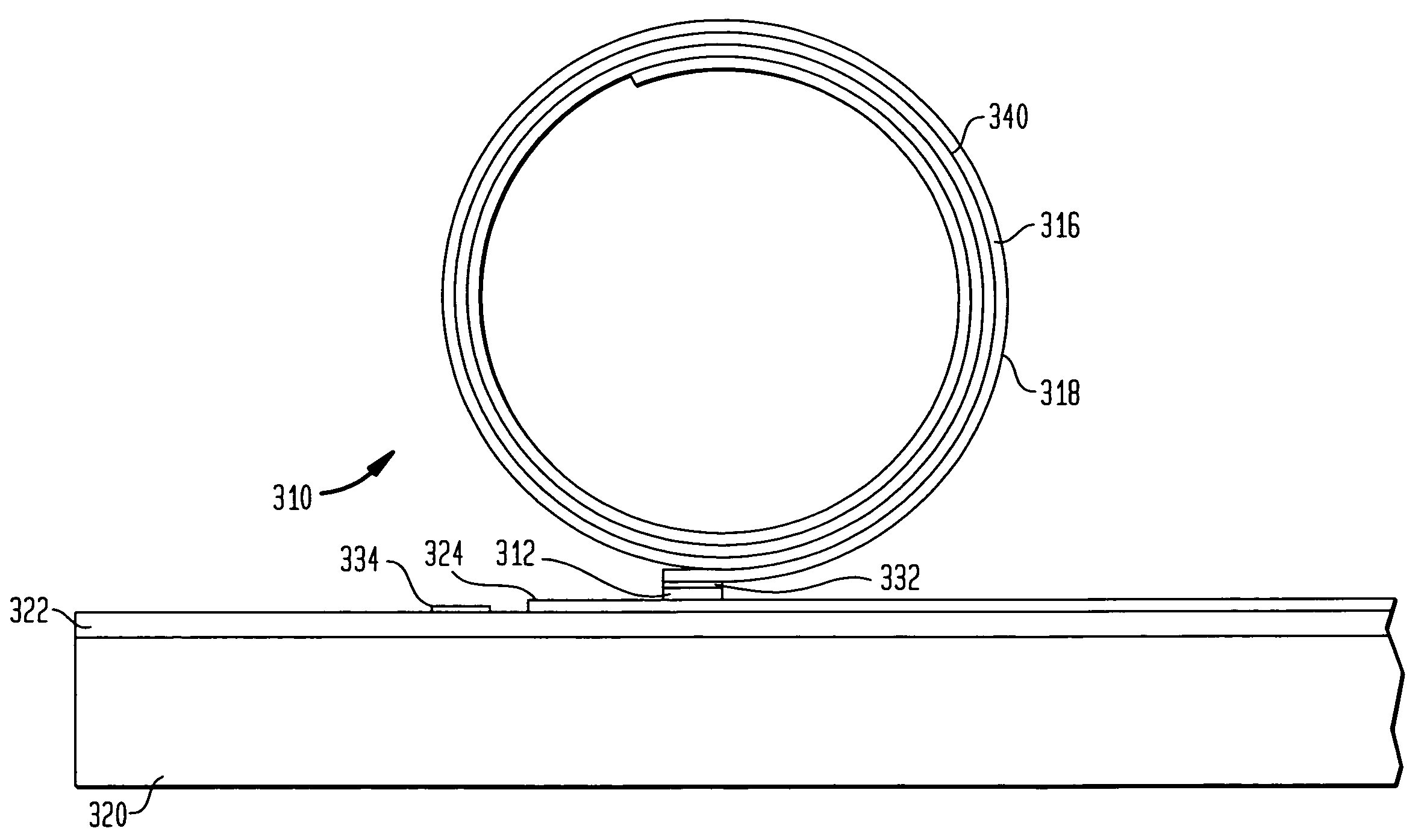
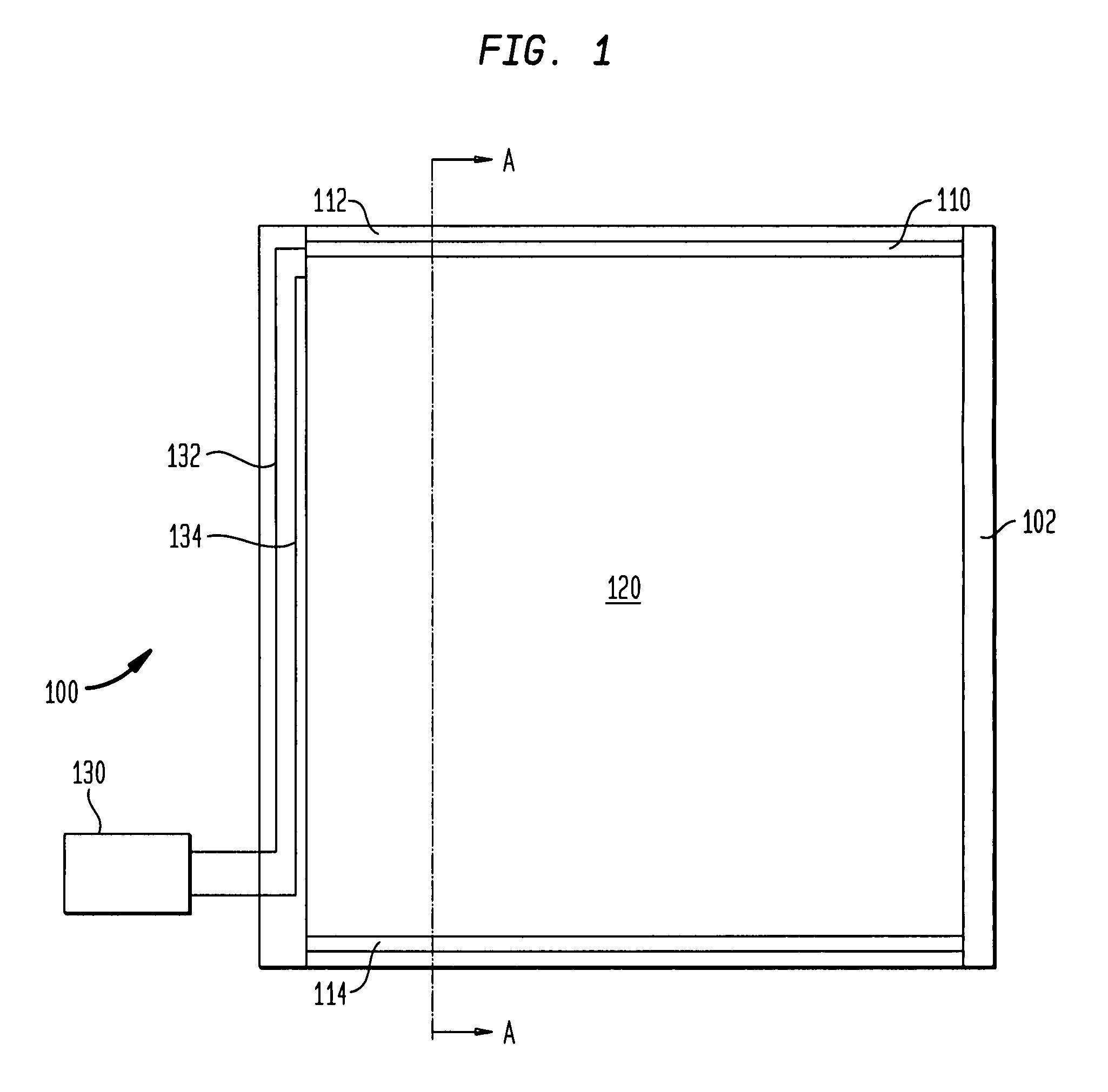
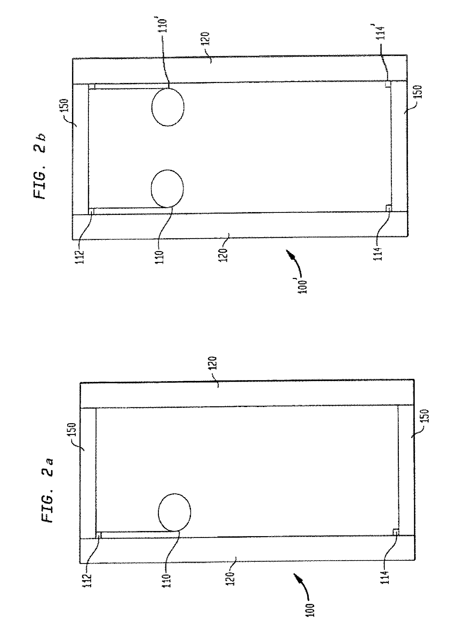
[0033]The present invention overcomes the disadvantages of existing insulated glazing units (IGUs), such as are used currently in energy efficient windows, by incorporating an electrically controlled, extremely thin physical electropolymeric shutter between the glazing panes of the IGU. The electropolymeric shutter of the invention provides improvements in functionality, reliability and manufacturability over known electropolymeric shutter devices, for example, in the display pixels of existing electropolymeric display (EPD) technology, specifically by providing the glazing applications such as are described herein. Known shutter devices are described in U.S. Pat. No. 4,266,339 (titled “Method for Making Rolling Electrode for Electrostatic Device” and issued May 12, 1981 to Charles G. Kalt), U.S. Pat. No. 5,231,559 (titled “Full Color Light Modulating Capacitor” and issued Jul. 27, 1993 to Kalt, et al.), U.S. Pat. No. 5,519,565 (titled “Electromagnetic-Wave Modulating, Movable Elect...


PUM


Abstract

An insulated glazing unit has controllable radiation transmittance. Peripheries of first and second glazing panes are attached and spaced apart facing each other and then attached to a supporting structure. A conductive layer is atop the first glazing pane inner surface as a fixed position electrode. A dielectric is atop the conductive layer. A coiled spiral roll, variable position electrode is between the first and second glazing panes, a width of its outer edge attached to the dielectric. A first electrical lead is connected to the variable position electrode's conductive layer. A second electrical lead is connected to the conductive layer atop the first glazing pane. Applied voltage between the first and second electrical leads creates a predetermined potential difference between the electrodes, and the variable position electrode unwinds and rolls out to at least partially cover the first glazing pane, at least reducing the intensity of passing radiation.

Description

CROSS-REFERENCE TO RELATED APPLICATIONS[0001]This application claims the benefit of the filing date of U.S. Provisional Application No. 60 / 859,637, filed Nov. 17, 2006, the disclosure of which is incorporated by reference herein.BACKGROUND OF THE INVENTION[0002]The invention relates to an insulated glazing unit (IGU) and its manufacture and, more particularly, to an IGU which includes an electronic physical shutter device that controls the intensity of radiation passing through the insulated glazing unit and / or that can block the radiation passing through the insulated glazing unit.[0003]Glass windows, skylights, doors, and the like which are used in buildings and other structures are known to waste large amounts of energy. The windows permit the infrared radiation of sunlight to pass into the interior of the building and cause unwanted heating, particularly during summer months, thus requiring increased use of air conditioning to remove the unwanted heat. The windows also permit he...

Claims


Application Information

Patent Timeline
Patent Type & Authority Patents(United States)
IPC IPC(8): G01J1/44G02B26/02
CPCE06B9/24E06B2009/2464
Inventor SCHLAM, ELLIOTTSLATER, MARK S.
Owner GUARDIAN GLASS LLC
Why Eureka
Try Eureka