Surface acoustic wave resonator and surface acoustic wave filter using the same
a surface acoustic wave and resonator technology, applied in piezoelectric/electrostrictive/magnetostrictive devices, piezoelectric/electrostriction/magnetostriction machines, electrical equipment, etc., can solve the problems of limiting the improvement of insertion loss and steepness, and the inability to secure the q-factors of the resonator, so as to improve the steepness of the filter characteristic and reduce the insertion loss
- Summary
- Abstract
- Description
- Claims
- Application Information
AI Technical Summary
Benefits of technology
Problems solved by technology
Method used
Image
Examples
embodiment 1
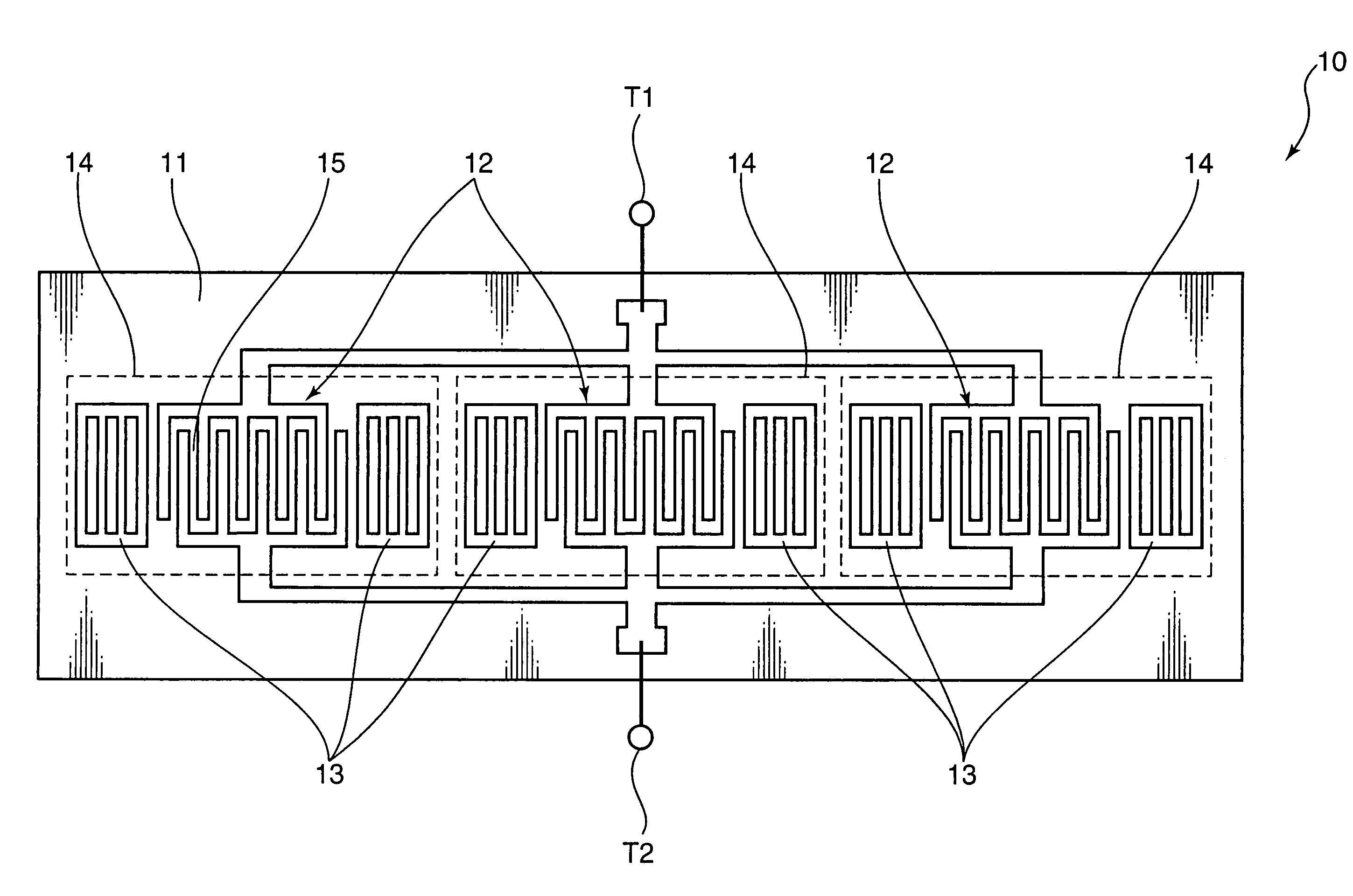
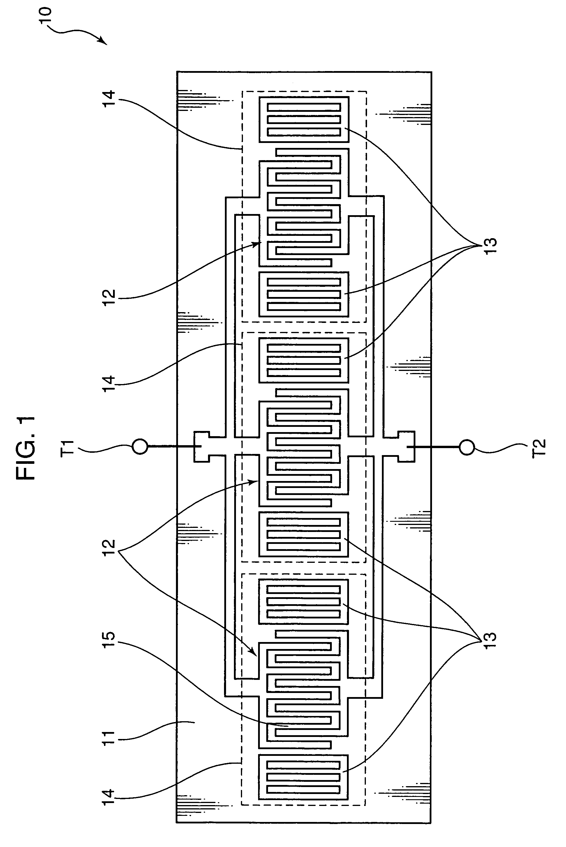
[0024]Hereinafter, Embodiment 1 of the present invention will be described. FIG. 1 is a diagram showing an exemplary structure of a surface acoustic wave resonator 10 according to Embodiment 1 of the present invention. The surface acoustic wave resonator 10 shown in FIG. 1 is a so-called one-port resonator. The surface acoustic wave resonator 10 includes a signal input terminal T1 for receiving a signal input from the outside, a signal output terminal T2 for outputting a signal to the outside, and a piezoelectric substrate 11 formed of 39° Y-cut, X-propagating lithium tantalate. On a surface of the piezoelectric substrate 11, three surface acoustic wave resonators 14 (surface acoustic wave resonators) are formed in line on the same surface acoustic wave propagation path.
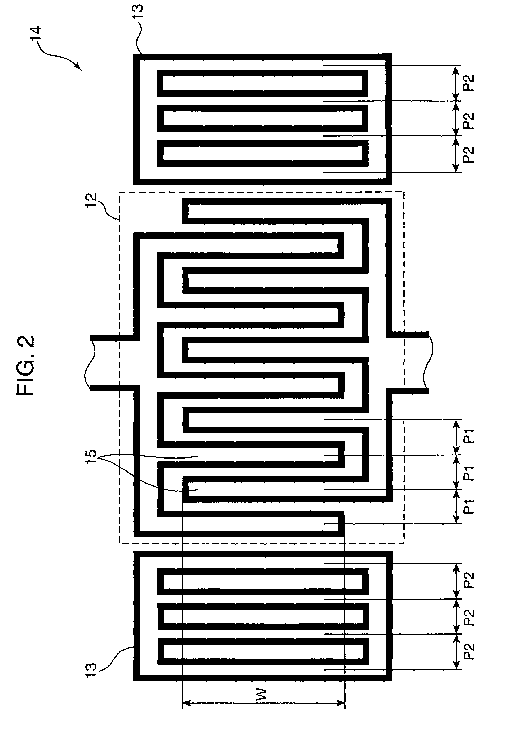
[0025]Each of the surface acoustic wave resonators 14 includes an IDT 12 and two reflectors 13 (reflecting electrodes) being adjacent to both ends of the IDT 12. Three surface acoustic wave resonators 14 having the s...
embodiment 2
[0060]Hereinafter, Embodiment 2 of the present invention will be described. In Embodiment 1 of the present invention, a structure of a surface acoustic wave resonator is shown. Embodiment 2 is different from Embodiment 1 in that a structure of a ladder-type surface acoustic wave filter using such a surface acoustic wave resonator is shown.
[0061]FIG. 10 is a diagram showing an exemplary structure of a surface acoustic wave filter 21 according to Embodiment 2 of the present invention. The surface acoustic wave filter 21 shown in FIG. 10 is an example of a ladder-type surface acoustic wave filter, and includes a signal input terminal T1 for receiving a signal input from the outside, a signal output terminal T2 for outputting a signal to the outside, a ground terminal T3 for ground connection, and a piezoelectric substrate 11 formed of 39° Y-cut, X-propagating lithium tantalate. On a surface of the piezoelectric substrate 11, a series resonator 16 and a parallel resonator 17 are formed....
embodiment 3
[0070]Hereinafter, Embodiment 3 of the present invention will be described. Embodiment 3 is different from Embodiment 2 in that, while Embodiment 2 relates to a ladder-type surface acoustic wave filter using one terminal pair surface acoustic wave resonator, Embodiment 3 is applied to a surface acoustic wave filter using a multiple-port surface acoustic wave resonator.
[0071]FIG. 12 shows an exemplary structure of a surface acoustic wave filter 22 according to Embodiment 3 of the present invention. The surface acoustic wave filter 22 shown in FIG. 12 is an example of a ladder-type surface acoustic wave filter, and includes a signal input terminal T1 for receiving a signal input from the outside, a signal output terminal T2 for outputting a signal to the outside, a ground terminal T3 for a ground connection, and a piezoelectric substrate 11 formed of 39° Y-cut, X-propagating lithium tantalate. On a surface of the piezoelectric substrate 11, a multiple-port surface acoustic wave resona...
PUM
 Abstract
Description
Claims
Application Information
 - R&D
- Intellectual Property
- Life Sciences
- Materials
- Tech Scout
- Unparalleled Data Quality
- Higher Quality Content
- 60% Fewer Hallucinations
Browse by: Latest US Patents, China's latest patents, Technical Efficacy Thesaurus, Application Domain, Technology Topic, Popular Technical Reports.
© 2025 PatSnap. All rights reserved.Legal|Privacy policy|Modern Slavery Act Transparency Statement|Sitemap|About US| Contact US: help@patsnap.com


