System and method for steam-assisted gravity drainage (SAGD)-based heavy oil well production

a technology of gravity drainage and heavy oil wells, applied in the direction of drilling accessories, fluid removal, insulation, etc., can solve the problems of poor productivity or tight project schedule, and achieve the effect of reducing the amount of work on site, tight project schedule, and poor productivity

Inactive Publication Date: 2010-01-19
TSILEVICH MAOZ BETZER
View PDF1 Cites 13 Cited by
  • Summary
  • Abstract
  • Description
  • Claims
  • Application Information

AI Technical Summary

Benefits of technology

[0024]The present invention provides a system and method for a well site complex facility for producing heavy oil or bitumen economically by steam-assisted gravity drainage. This system is particularly applicable if the oil reservoir is in a remote location and subject to extreme weather. The present invention provides the ability to construct the gathering and injection systems in a shop so as to minimize the amount of work on-site. The present invention is designed for locations where the work on-site is expensive and would result in poor productivity or a tight project schedule. The present invention is particularly applicable to the oil sands deposits in north Alberta and Saskatchewan in Canada and possibly in other locations.
[0028]The main difference between the use of a single basic module unit (a production unit and an injection unit) and a double basic module unit (or even a multiple basic module unit) is due to transportation limits. There is an advantage to transport a single basic unit as it is easier and can be done from longer distances using more standard transportation means, however the disadvantages is that it will increase the amount of work on site because there will be double the amount of basic module platform unit to connect on site. On the other hand the use of the double platform (or even a multiple platform) units have site advantages by reducing the amount of work on site but it have transportation limitations that increase the transportation cost and limit the possible off site production shops that can ship those big units to site. The decision to use the single basic unit, the double basic unit or even a multiple basic unit should be done on a specific basis for the specific heavy oil project.

Problems solved by technology

The present invention is designed for locations where the work on-site is expensive and would result in poor productivity or a tight project schedule.

Method used


Image

  • System and method for steam-assisted gravity drainage (SAGD)-based heavy oil well production
  • System and method for steam-assisted gravity drainage (SAGD)-based heavy oil well production
  • System and method for steam-assisted gravity drainage (SAGD)-based heavy oil well production

Examples


Embodiment Construction

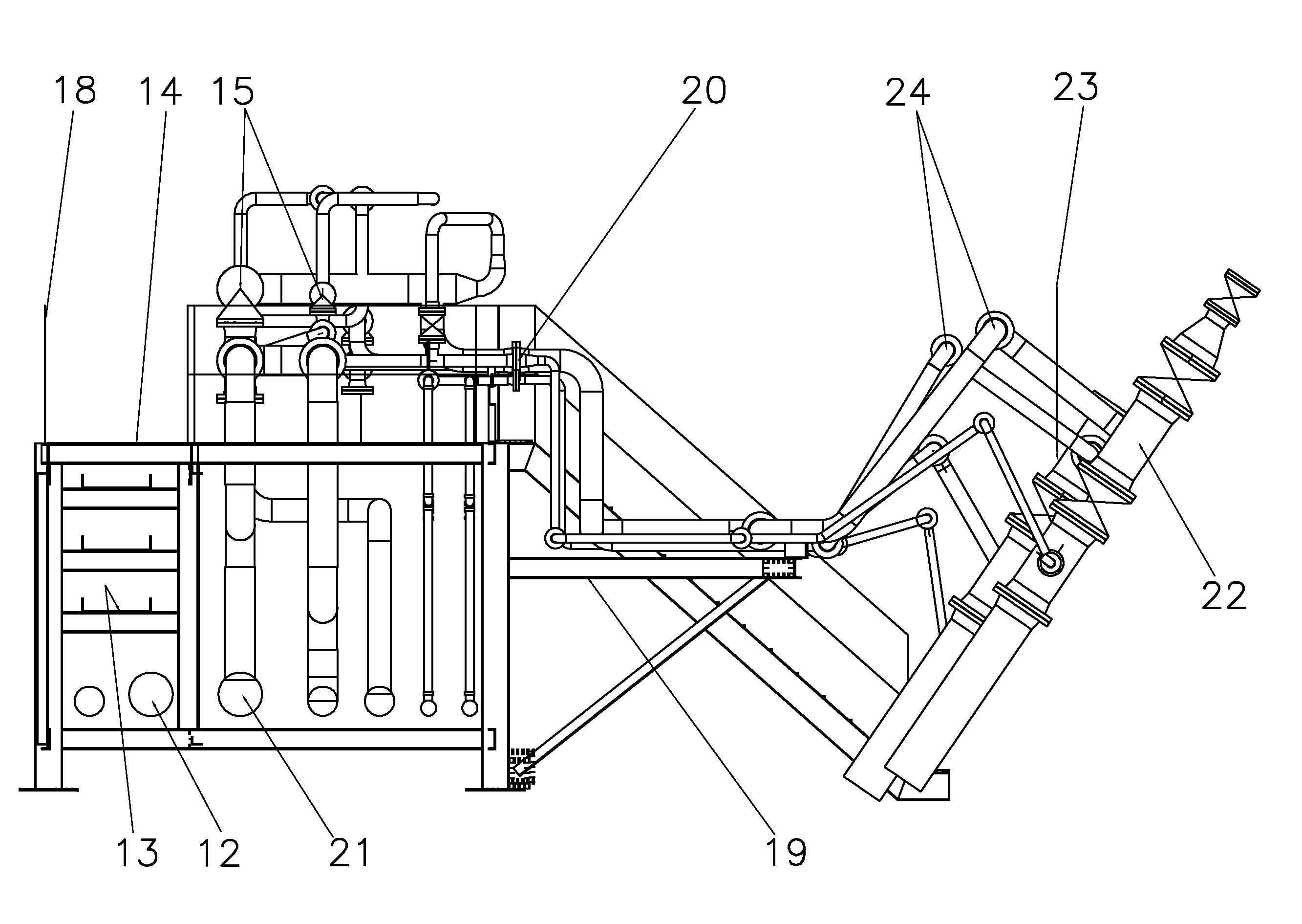
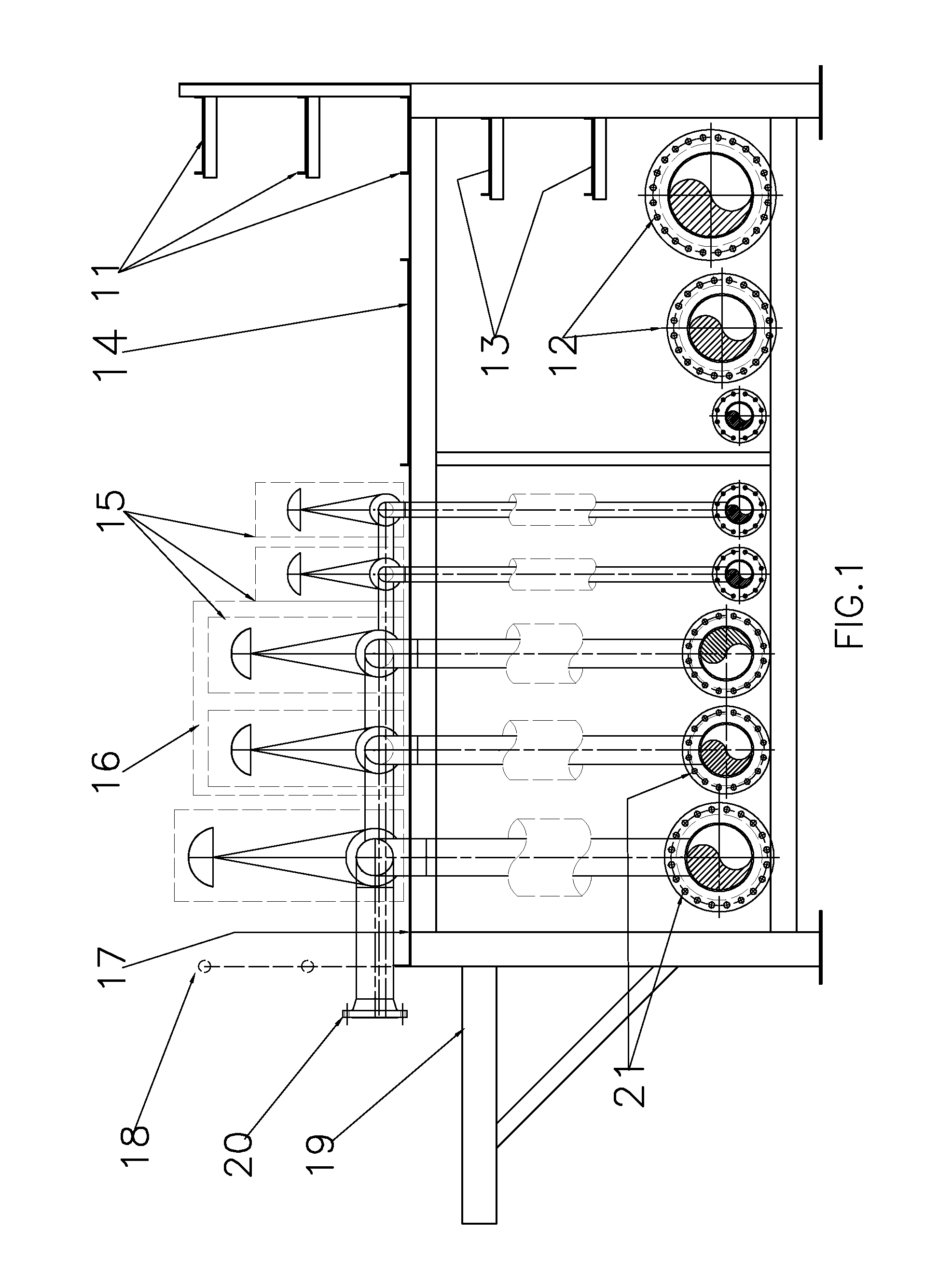
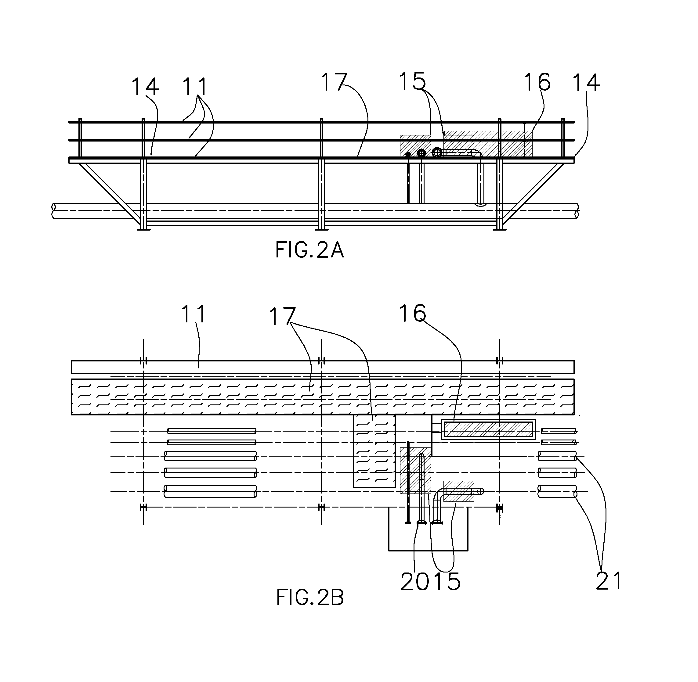
[0041]FIG. 1 shows a basic platform unit cross-section viewed from the connection area between two basic platform units. The first level contains the injection and production pipes 21 that are connected to the second level. In additional to that, there is an expansion option for additional flow lines 12 that are not connected to the second level and additional cable trays 13. As such, the platform can serve as a pipe-rack for product which is not connected directly with the wells on the pads. The second level of FIG. 1 shows the cable trays 11 that provide, together with cable trays 13, the electrical and instrumentation connection to the platform. Walkway 14 provides access to the valves, controllers and instrumentation that will serve the platform. The valves, flow controls and instrumentation are located on the second level in designated areas 15 while the electronic instrumentations are located in another designated area 16. The valves, the flow control instrumentation and the e...


PUM


Abstract

A system for steam-assisted gravity drainage for heavy oil production has a first well, a second well, a first platform connected to the well head of the first well so as to inject steam into the first well, and a second platform connected to the well head of the second well for producing heavy oil from the second well. The platforms are arranged in parallel flow relationship. Each of the platform has a first level with flow lines extending longitudinally therealong and a second level located above the first level and having piping connected to the flow lines of the first level. The second level includes valves and controllers cooperative with the piping. The platforms are modular in nature and can be connected to other platforms.

Description

CROSS-REFERENCE TO RELATED U.S. APPLICATIONS[0001]Not applicable.STATEMENT REGARDING FEDERALLY SPONSORED RESEARCH OR DEVELOPMENT[0002]Not applicable.NAMES OF PARTIES TO A JOINT RESEARCH AGREEMENT[0003]Not applicable.REFERENCE TO AN APPENDIX SUBMITTED ON COMPACT DISC[0004]Not applicable.BACKGROUND OF THE INVENTION[0005]1. Field of the Invention[0006]The present invention relates to methods and systems for producing crude oil from a reservoir of heavy oil or bitumen by steam-assisted gravity drainage (SAGD) processes. More particularly, the present invention relates to the injection, for production and gather systems, of field wells by using basic block units as a building block that could be installed with minimal cost and minimal on-site labor. More particularly, the present invention relates to modular systems that can be employed in such SAGD processes.[0007]2. Description of Related Art Including Information Disclosed Under 37 CFR 1.97 and 37 CFR 1.98[0008]Heavy oil reservoirs co...

Claims


Application Information

Patent Timeline
Patent Type & Authority Patents(United States)
IPC IPC(8): E21B43/24
CPCE21B43/2406
Inventor TSILEVICH, MAOZ BETZER
Owner TSILEVICH MAOZ BETZER
Why Eureka
Try Eureka