
Beam-steering apparatus having five degrees of freedom of line-of-sight steering

a beam-steering apparatus and line-of-sight steering technology, which is applied in the direction of mountings, instruments, mirrors, etc., can solve the problems of large apparatuses that provide five degrees of freedom of beam-steering, difficult image analysis, and high cost, so as to keep the size and mass of the beam-steering apparatus small, low power consumption, and low inertia

Active Publication Date: 2010-01-19
RAYTHEON CO
View PDF5 Cites 4 Cited by
  • Summary
  • Abstract
  • Description
  • Claims
  • Application Information

AI Technical Summary

Benefits of technology

The present invention provides a beam-steering apparatus that allows for five degrees of freedom of the steering of a line-of-sight output beam or input beam. This is achieved by using three to five planar tiltable mirrors that can be tilted about one axis of rotation or two axes of rotation that lie in the plane of the mirror. The use of only mirrors simplifies the apparatus and reduces the weight, size, and complexity of the required components. The apparatus can be used in various applications and offers flexibility in design.

Problems solved by technology

A more complex problem arises where the line-of-sight must be steered in more than two degrees of freedom, and as many as five degrees of freedom.
For example, if the system includes a focal plane array detector and the movement of the imaging optics causes the image on the focal plane array to rotate, the analysis of the image may become more difficult.
The resulting apparatus that provides five degrees of freedom of the beam steering is large, heavy, and complex, because it requires that a portion of the apparatus rotates as an assembly about the line of sight.

Method used


Image

  • Beam-steering apparatus having five degrees of freedom of line-of-sight steering
  • Beam-steering apparatus having five degrees of freedom of line-of-sight steering
  • Beam-steering apparatus having five degrees of freedom of line-of-sight steering

Examples


Embodiment Construction

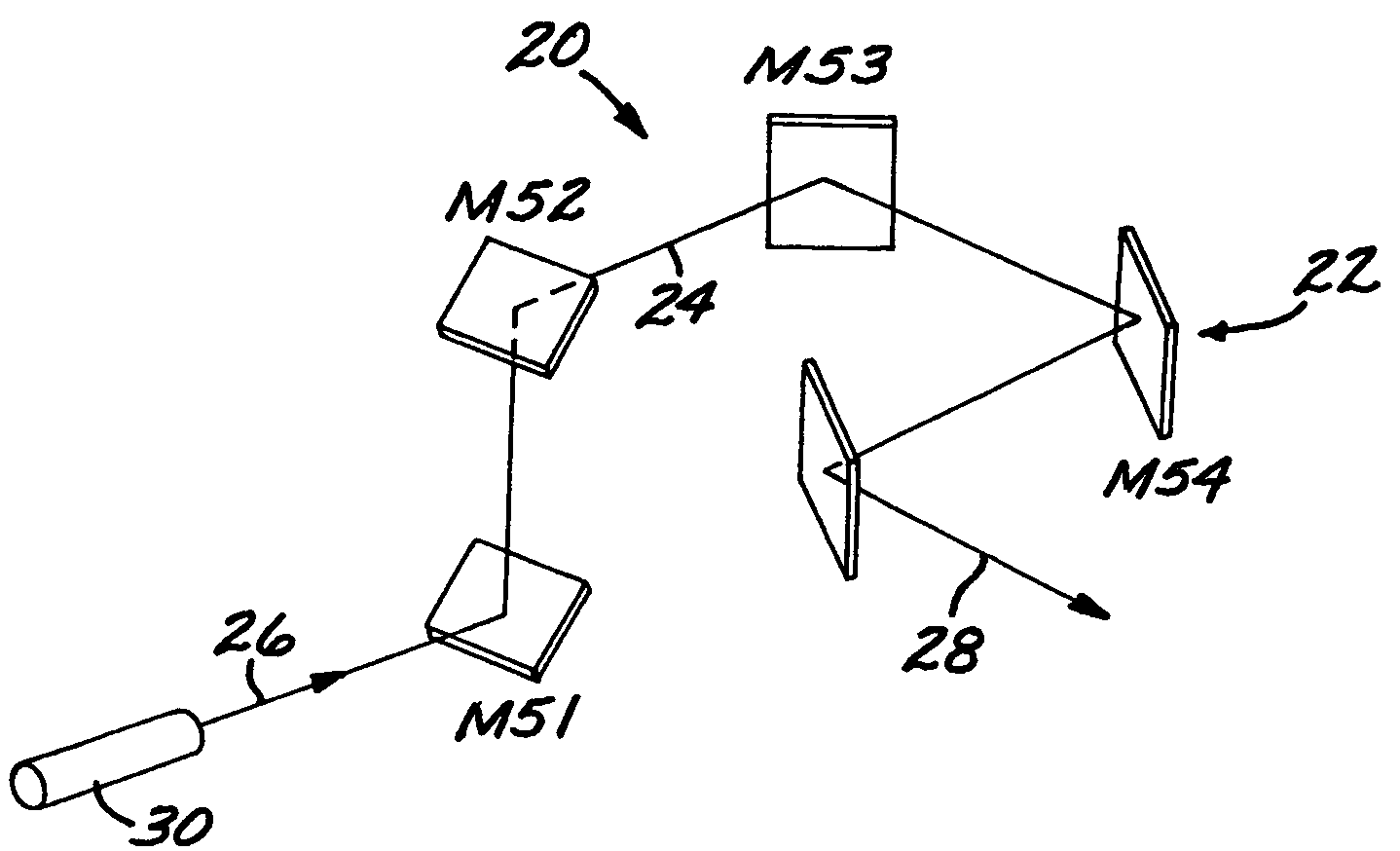
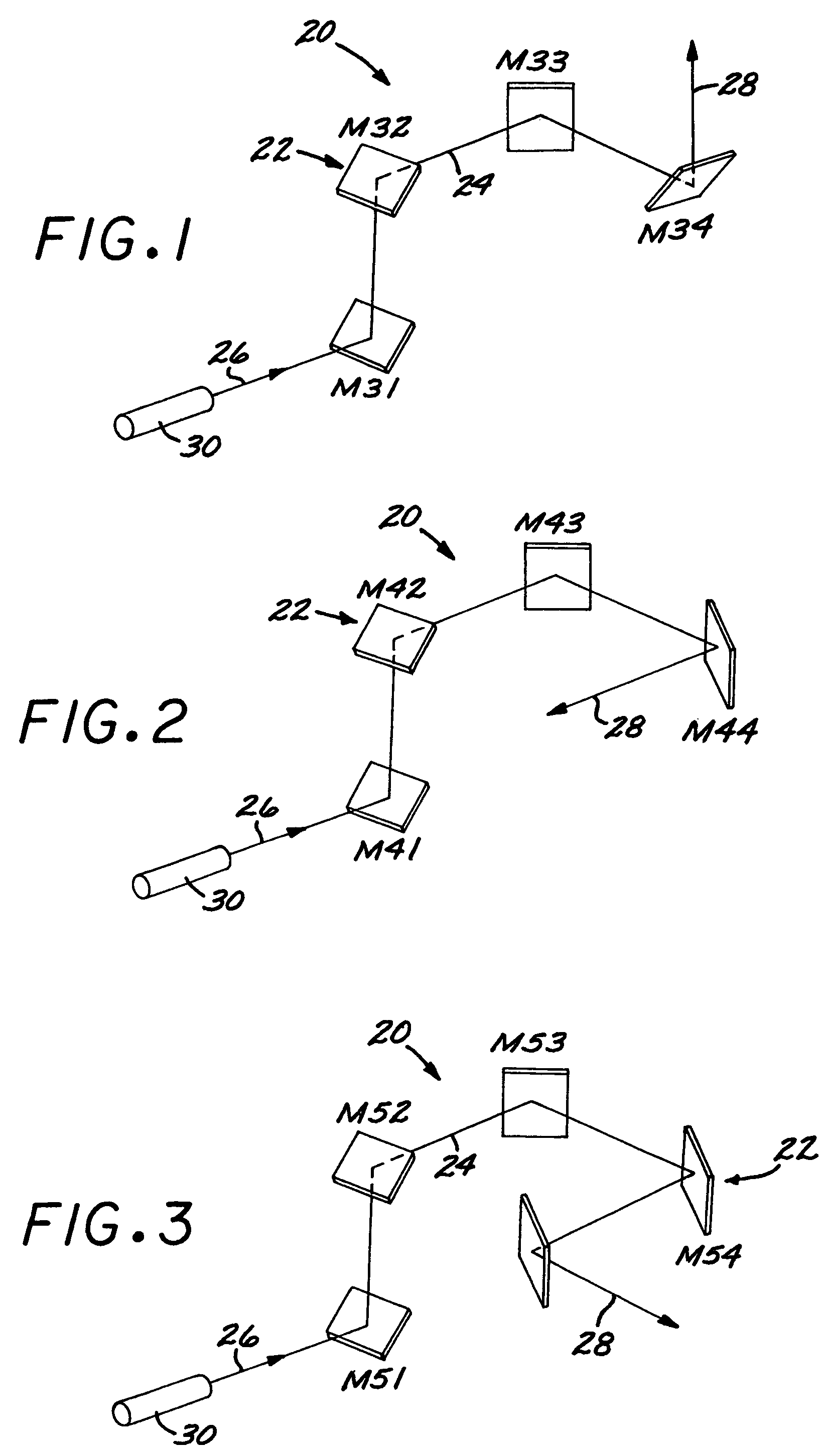
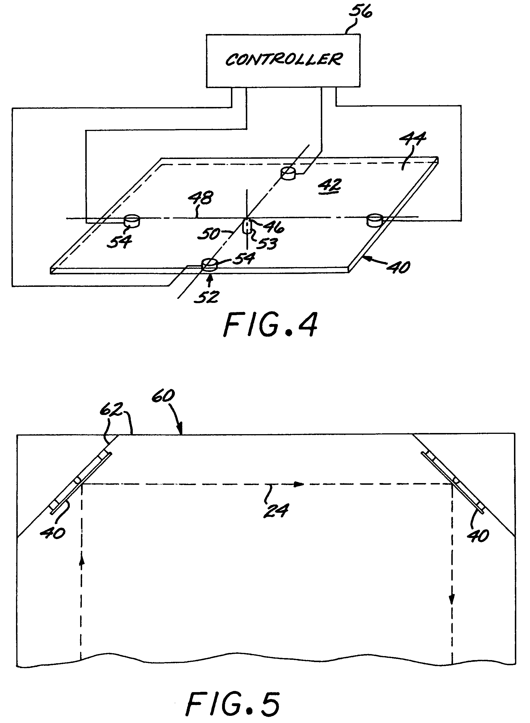
[0028]Each of FIGS. 1, 2, and 3 depicts an example of a five-degree-of-freedom beam-steering apparatus 20. The beam steering apparatus 20 includes a set22 of planar tiltable mirrors. The planar mirrors of the set 22 of planar tiltable mirrors are positioned to define a radiation (usually light) beam path 24 that reflects therebetween with a light input 26 to the set 22 of mirrors and a light output 28 from the set 22 of mirrors. There is typically a light transceiver 30 at the light input 26 or the light output 28. If the light transceiver 30 is at the light input 26 as illustrated in the figures, the light transceiver 30 is preferably a light source such as a laser. If the light transceiver 30 is at the light output 28, the light transceiver 30 is preferably a light receiver such as an imaging detector. For clarity, the following discussion will address the case where the light transceiver 30 is a light source, so that the light output 28 is the steerable line-of-sight beam. Under ...


PUM


Abstract

A beam-steering apparatus comprises a set of planar tiltable mirrors positioned to define a light beam path therebetween. The set of planar tiltable mirrors comprises from three to five planar tiltable mirrors. Each of the planar tiltable mirrors has a center of rotation lying in a plane of the mirror and each of the planar tiltable mirrors is tiltable about one axis of rotation or two orthogonal axes of rotation that lie in the plane of the mirror. The total number of axes of rotation about which the planar tiltable mirrors of the set of planar tiltable mirrors can tilt is at least five. A mirror drive system tilts each respective planar mirror about its respective axis of rotation or axes of rotation. With this apparatus, an input or output light beam path is steerable over two angular, one rotational, and two lateral-position degrees of freedom.

Description

[0001]This invention relates to the steering of the line-of-sight of a beam such as a light beam and, more particularly, to apparatus that provides five degrees of freedom of line-of-sight steering using only planar tiltable mirrors.BACKGROUND OF THE INVENTION[0002]In many applications, a radiation source (such as a laser) or a detector (such as a focal plane array or FPA) is maintained stationary, and the output beam of the radiation source or the input beam of the detector is aimed in a desired direction using a reflective and / or refractive beam-steering apparatus. Thus, for example, an image generator may remain stationary, and the output image beam is aimed by movable mirrors and / or lenses. Similarly, an imaging focal plane array detector may remain stationary, and the area of space to be imaged is selected by movable mirrors and / or lenses.[0003]Familiar types of beam-steering apparatus include azimuth-elevation, roll-nod, and roll-pitch gimbals. The rotation of the gimbaled str...

Claims


Application Information

Patent Timeline
Patent Type & Authority Patents(United States)
IPC IPC(8): G02B5/08
CPCG02B7/1821G02B26/0816G02B26/105G02B26/101
Inventor COOK, LACY G.
Owner RAYTHEON CO
Learn More