Ceramic substrate, ceramic package for housing light emitting element

a technology of ceramic packaging and ceramic substrate, which is applied in the field of ceramic substrate and ceramic package for housing light emitting elements, can solve the problems that light cannot be efficiently reflected from the light emitting element mounted, and achieve the effects of reducing the smoothness of the metallic layer surface, reducing the cost, and peeling

Inactive Publication Date: 2010-01-19
NGK SPARK PLUG CO LTD
View PDF20 Cites 14 Cited by
  • Summary
  • Abstract
  • Description
  • Claims
  • Application Information

AI Technical Summary

Benefits of technology

[0009]In the invention, the ceramic substrate comprises a metallic layer on its surface, and the metallic layer includes a multiplicity of different metal layers containing metallic materials of different kinds, the metallic layer including a silver layer containing silver, a gold layer containing gold which is a metal other than silver and nobler than nickel, and a nickel layer containing nickel provided in the recited order from the outermost layer. Thus, the gold layer is interposed between the nickel layer and the silver layer so that both the bonding strength between the nickel layer and the gold layer and the bonding strength between the gold layer and the silver layer are made higher than the bonding strength between the nickel layer and the silver layer. As a result, it is possible to prevent the pealing between the individual layers (e.g., the gold layer and the outermost silver layer) arranged on the nickel layer, more reliably, as might otherwise be caused a thermal stress or the like. This improvement in the bonding strength is expected to come from that the anchoring effect got by the immigration of silver atoms into the gold-plated layer in the interface between the gold layer and the silver layer and the anchoring effect got by the immigration of the gold atoms into the nickel layer in the interface between the nickel layer and the gold layer are more effective than the anchoring effect got in the layer configuration of the prior art by the immigration of the silver atoms into the nickel layer in the interface between the nickel layer and the silver layer. The nickel layer contains nickel as a main component and may be a layer containing a nickel alloy containing a metal other than nickel. The gold layer contains gold as a main component and may be a layer containing a gold alloy containing a metal other than gold. The silver layer contains silver as a main component (e.g., 50 weight % or more) and may be a layer containing a silver alloy containing a metal other than silver.
[0026]According to this, most of the light irradiated at a predetermined angle on the silver layer of that surface roughness is regularly reflected on the smooth surface of that silver layer so that the light emitted from the light emitting element to be later mounted on the bottom face of the cavity can be reflected more efficiently and reliably.

Problems solved by technology

As a result, there is a problem that the light cannot be efficiently reflected from the light emitting element mounted.

Method used


Image

  • Ceramic substrate, ceramic package for housing light emitting element
  • Ceramic substrate, ceramic package for housing light emitting element
  • Ceramic substrate, ceramic package for housing light emitting element

Examples


Embodiment Construction

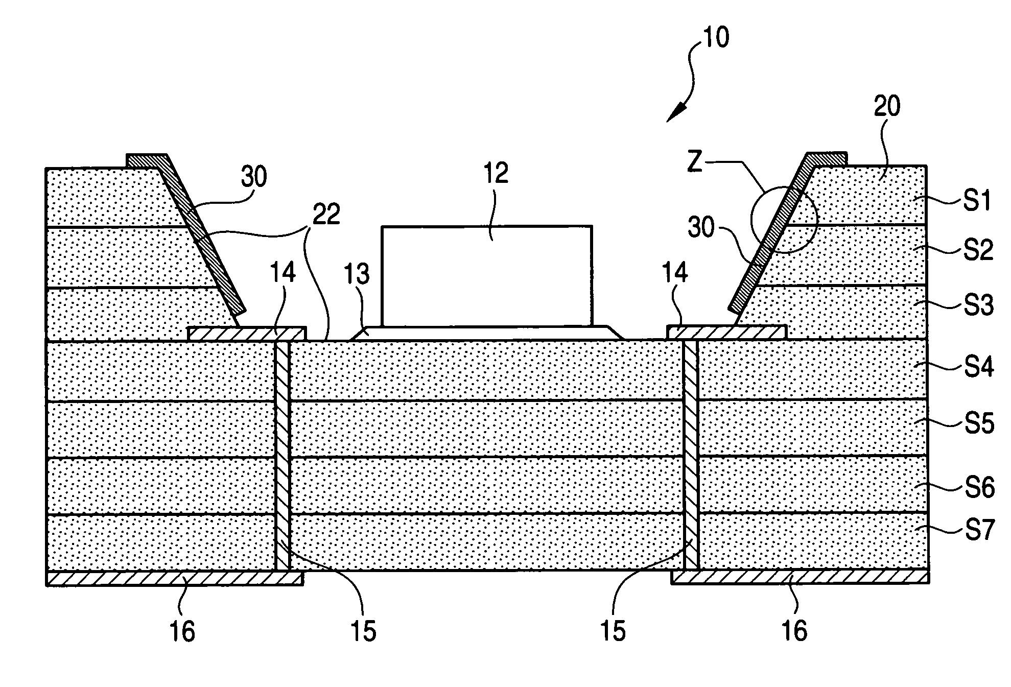
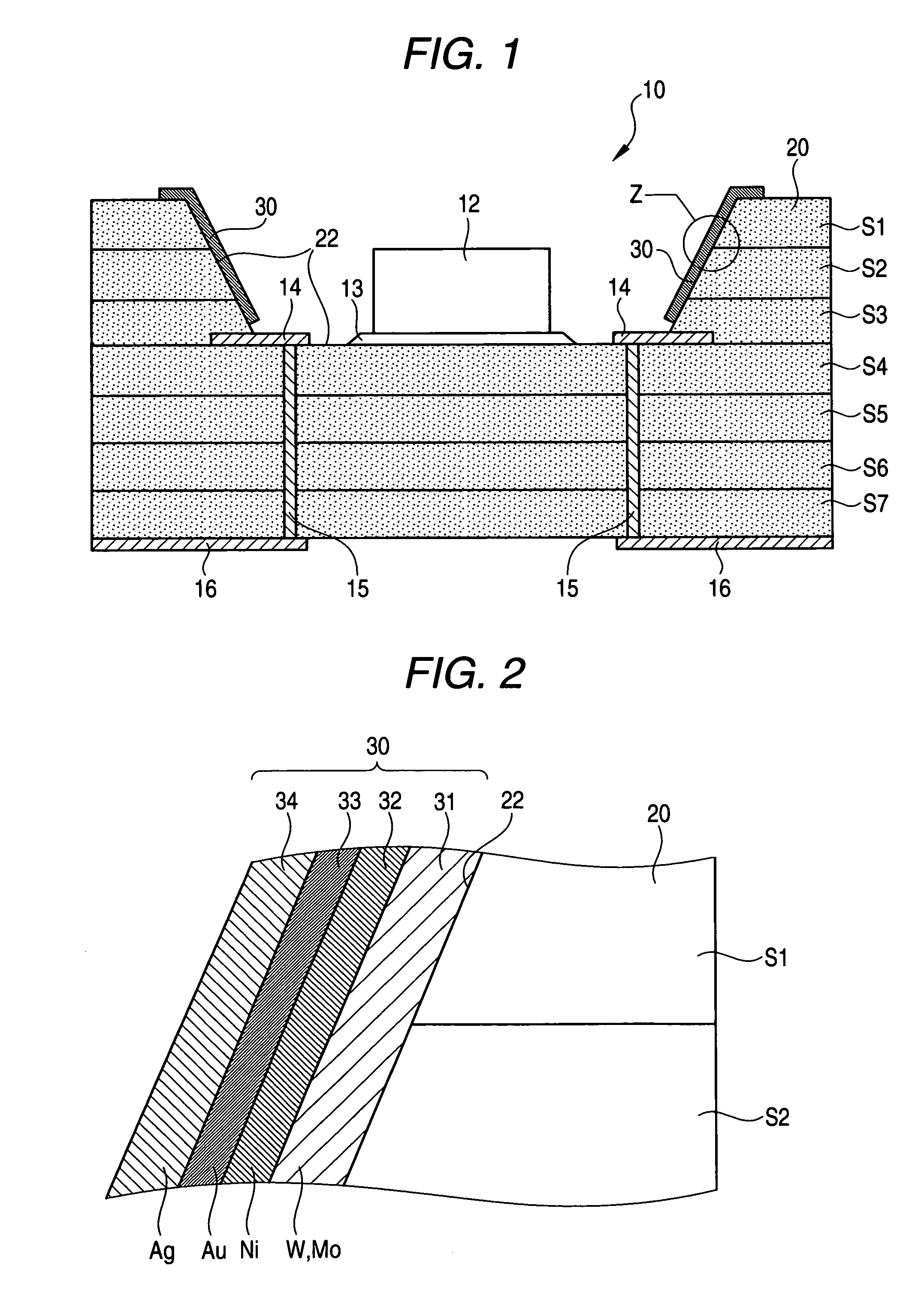
[0057]In order to clarify the configuration and actions of the invention thus far described, here is described an embodiment of the invention. FIG. 1 is an explanatory view presenting a section of the essential portion of a ceramic package 10 for housing light emitting element according to an embodiment of the ceramic substrate of the invention. FIG. 2 is an explanatory view schematically showing a Z-portion in FIG. 1 in an enlarged scale.

[0058]As shown, the ceramic package 10 for housing light emitting element is equipped with a substrate body 20 configured by laminating ceramic layers, a cavity 22 opened in the surface of the substrate body 20, and a metallic layer 30 formed continuously along the surface of the substrate body 20. A conductive electrode layer 14 is formed on the bottom face of the cavity 22 formed in that substrate. A light emitting element 12 is housed in that cavity. The substrate body 20 is formed by laminating ceramic layers S1 to S7, which are mainly composed...


PUM

PropertyMeasurementUnit
thicknessaaaaaaaaaa
thicknessaaaaaaaaaa
thicknessaaaaaaaaaa

Abstract

A ceramic substrate comprising a metallic layer on its surface, wherein said metallic layer includes: a silver layer containing silver; a gold layer containing gold; and a nickel layer containing nickel, in this order from an outermost layer of said metallic layer.

Description

FIELD OF THE INVENTION[0001]The present invention relates to a ceramic substrate having a metallic layer on its surface and to a ceramic package for housing a semiconductor element such as a light emitting element.BACKGROUND OF THE INVENTION[0002]In recent years, ceramics has electric properties such as insulating or dielectric properties so that it is used as a material for electronic parts such as ceramic packages. These electronic parts are configured by housing semiconductor elements (e.g., diodes as light emitting elements, thyristors or transistors) in the ceramic package and by arranging circuits or the like to be connected with the semiconductor elements in the package body. When such circuits are to be arranged, a metallic layer for functioning as a circuit pattern may have to be formed on the surface of the package body by using a conductor such as copper or silver. In order to reflect the light efficiently from the light emitting element, the metallic layer for functionin...

Claims


Application Information

Patent Timeline
Patent Type & Authority Patents(United States)
IPC IPC(8): B32B15/00H01L33/48H01L33/60
CPCH05K1/0274H05K3/246H01L33/60H01L33/486Y10T428/26H05K1/0306H05K1/092H05K1/183H05K3/403H05K2201/0347H05K2201/09781H05K2201/10106H05K2201/2054H01L2224/32225H01L2224/48091H01L2224/73265H01L2224/92247Y10T428/12819Y10T428/12826Y10T428/12576H01L2224/48235H01L2924/1301Y10T428/12528Y10T428/12806Y10T428/12868Y10T428/12875Y10T428/1284Y10T428/1317Y10T428/12361Y10T428/12889Y10T428/131Y10T428/12611Y10T428/12861Y10T428/12903Y10T428/12896Y10T428/12944Y10T428/265Y10T428/12639H01L2924/00014H01L2924/00
Inventor WAKAKO, HISASHINAGAI, MAKOTOUCHIDA, ATSUSHIMORITA, MASAHITOKIMURA, KAZUO
Owner NGK SPARK PLUG CO LTD
Why Eureka
Try Eureka