Locomotive/train navigation system and method

a technology for locomotives and trains, applied in the direction of navigation instruments, navigation instruments, instruments, etc., can solve the problems of difficult and expensive accuracy ascertainment, non-uniformity of railroad tracks, and difficulty in resolving these disparities sufficiently to resolve to a specific track with a high degree of confiden

Active Publication Date: 2010-01-19
LOCKHEED MARTIN CORP
View PDF18 Cites 21 Cited by
  • Summary
  • Abstract
  • Description
  • Claims
  • Application Information

AI Technical Summary

Benefits of technology

[0007]In accordance with one aspect of the present invention, a mathematical “halo” is conceptually associated or assigned to one or more and preferably all transition points within the trackway system. As a locomotive having a navigation system (such as a combined inertial / GPS location system) moves along an initially known track and enters the “halo” surrounding a track transition, data collection / logging commences to accumulate successive position information data points as the locomotive moves into, progresses through, and exits the “halo.” The collected data for movement within the “halo” is then subject to a best fit assessment relative to the data pre-stored in the track database. In this assessment, emphasis is given to fitting the “relative geometry” of successive data points within the “halo” for that track transition and not to the absolute geo-position data. Since absolute geo-position information is discounted and relative information within the “halo” is determinative, best fit track identification from the database upon exiting the “halo” can be quickly resolved.

Problems solved by technology

In practice, however, weather and geographical conditions, train speeds, tonnage, and continued maintenance requirements contribute to railroad track non-uniformities.
Although the FRA (Federal Rail Administration) regulates the amount of track irregularities permitted for each track class (Class 1-7), most track database information carries errors that can change with time and which are often difficult to and expensive to ascertain with accuracy.
As is often the case, disparities arise between the output of the train / locomotive mounted location determining system and the corresponding database information; at times, the disparities can be such that resolving these disparities sufficiently to resolve to a specific track with a high degree of confidence can be difficult.

Method used


Image

  • Locomotive/train navigation system and method
  • Locomotive/train navigation system and method
  • Locomotive/train navigation system and method

Examples


Embodiment Construction

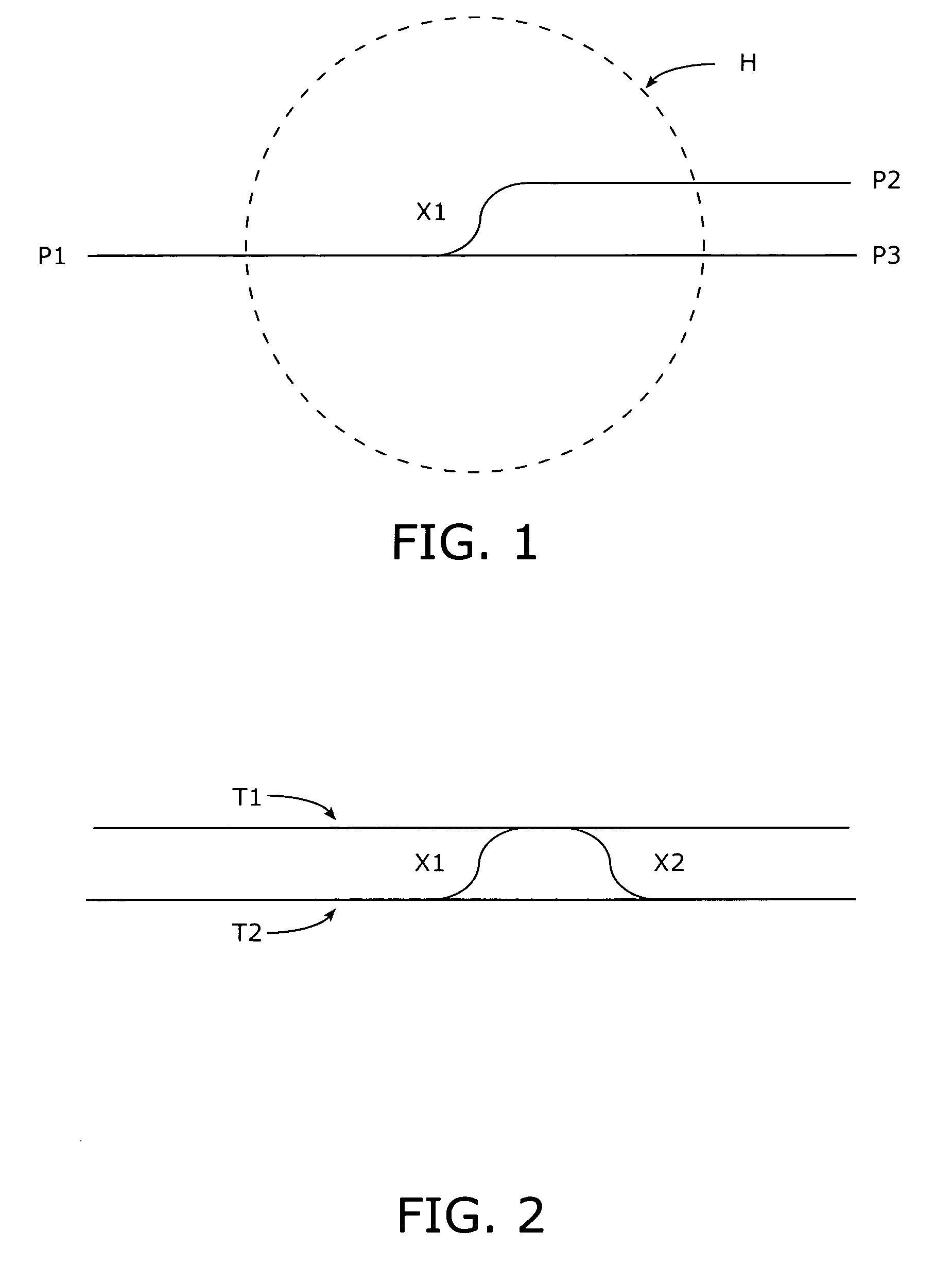
[0018]A representative track transition is shown in schematic form in FIG. 1 and includes a track segment extending between a point P1 on the left and a point P3 on the right; additionally, a cross-over section X1 interconnects the track between points P1 and P2 with a track that extends to point P3. The transition X1 can be a controllable switch, for example. Thus, in FIG. 1 a locomotive or train can proceed from point P1 on the left directly through to point P3 on the right or, alternatively, pass through transition X1 to the point P2 on the right. As is known in the art, track databases are maintained that include selected position information for sections of track and transition, features, or points of interest within the track system including latitude, longitude, azimuth (heading), and other information including elevation, inclination, and side-to-side tilt (i.e., roll). In general, these databases possess a coarse accuracy in terms of absolute latitude and longitude. As show...


PUM


Abstract

In a rail track system having transition points, a locomotive having a navigation system (such as a combined inertial / GPS location system) moves along an initially known track and enters the “halo” surrounding a track transition to begin data collection / logging to accumulate successive position information data points as the locomotive moves into, progresses through, and exits the “halo.” The collected data for movement within the “halo” is then subject to a best fit assessment relative to the data pre-stored in the track database.

Description

CROSS-REFERENCE TO RELATED APPLICATION[0001]This application claims the benefit of commonly owned U.S. Provisional Patent Application 60 / 677,332 filed by the inventor herein on May 4, 2005.BACKGROUND OF THE INVENTION[0002]The present invention relates to system and method for positionally locating a train / locomotive on a trackway system.[0003]Various systems have been developed to track the movement of and / or location of railway locomotives on track systems including the system disclosed in U.S. Pat. No. 6,641,090 issued Nov. 4, 2003 to Thomas J. Meyer and in common assignment herewith in which inertial components (including accelerometers and gyroscopes) cooperate with GPS information to provide location data.[0004]Track databases are maintained that store track information including the absolute and relative position of tracks and track transitions such as, for example, switches and turnouts. Ideally, railroad tracks are perfectly uniform and remain consistent with their original ...

Claims


Application Information

Patent Timeline
Patent Type & Authority Patents(United States)
IPC IPC(8): G05D1/00
CPCB61L25/021B61L25/025G01C21/005B61L2205/04
Inventor METZGER, THOMAS R.
Owner LOCKHEED MARTIN CORP
Why Eureka
Try Eureka