Liquid ejection head and image forming apparatus

a liquid ejection head and image forming technology, applied in the direction of printing, inking apparatus, etc., can solve the problems of high frequency, high resistance of liquid supply channels, and deformation of refilling characteristics, so as to simplify the composition of liquid supply channels and reduce flow channel resistance. , the effect of high density wires

Inactive Publication Date: 2010-01-26
FUJIFILM CORP
View PDF5 Cites 2 Cited by
  • Summary
  • Abstract
  • Description
  • Claims
  • Application Information

AI Technical Summary

Benefits of technology

[0016]The present invention is contrived in view of the foregoing circumstances, an object thereof being to provide a liquid ejection head and an image forming apparatus in which installation of high-density wiring can be achieved, and refilling characteristics can be improved.

Problems solved by technology

However, in a head formed to high density, the ink flow channels tend to become highly complicated.
As a result, the flow path resistance to the ink inside the head can increase, refilling characteristics can be degraded, it is difficult to eject high-viscosity ink at a high frequency, and consequently ink ejection becomes instable.
Furthermore, as the density of the head increases, the space for the electrical wires (internal wires) for driving the piezoelectric elements becomes insufficient, and the difficulty of wiring increases.
However, no consideration is given to a composition in which the piezoelectric elements are arranged in a two-dimensional configuration and the composition is not suitable for installation of high-density wiring.
However, the description only relates to a composition with one row of piezoelectric elements, and therefore, similarly to Japanese Patent Application Publication No. 9-314833, it is not suitable for installation of high-density wiring.
Moreover, if the head disclosed in Japanese Patent Application Publication No. 2003-127366 is formed to a high density, then the ink flow channels become complicated, and there is a possibility that the refilling characteristics decline.
In the head disclosed in Japanese Patent Application Publication No. 2001-179973, electrical wires (internal wires) extended from the electrodes of the piezoelectric elements to the end section of the head are disposed in the same plane as the diaphragm on which the piezoelectric elements are disposed, and hence there is a high possibility that problems occur in the electrical wires, and the composition is therefore unsuitable for achieving high density in the head.
Furthermore, the ink flow channels are composed by a plurality of bending channels, thus causing the refilling characteristics to decline, and making it difficult to eject high-viscosity ink at a high frequency.
In Japanese Patent Application Publication No. 2004-1550, there is no discussion of the method of installing the electrical wires (internal wires) for driving the piezoelectric elements, and there is a possibility that the above-described problems occur in these electrical wires.

Method used


Image

  • Liquid ejection head and image forming apparatus
  • Liquid ejection head and image forming apparatus
  • Liquid ejection head and image forming apparatus

Examples


first embodiment

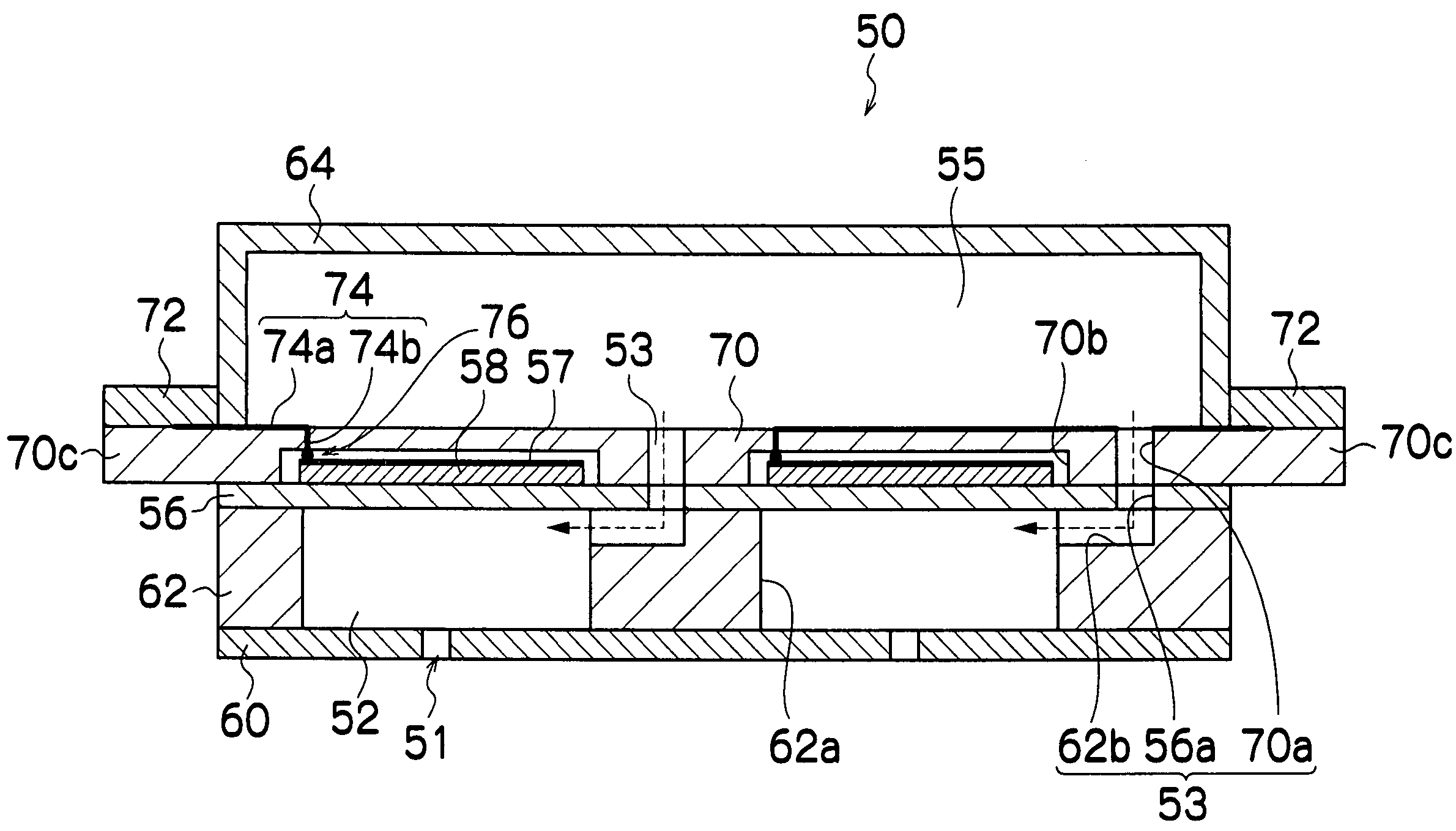
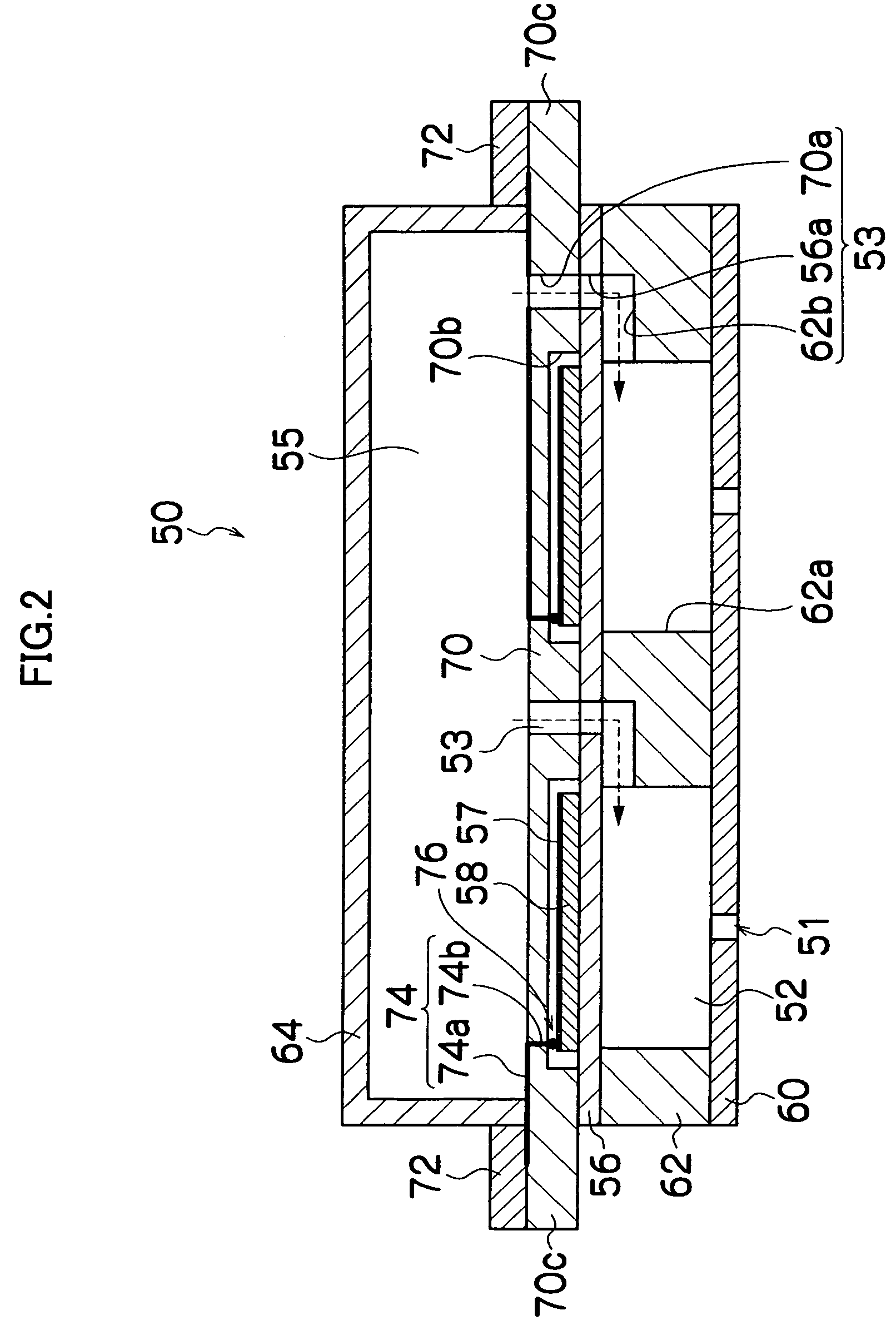
[0085]FIG. 2 is a cross-sectional diagram of the print head 50 relating to a first embodiment. The print head 50 relating to the present embodiment is a line head in which a plurality of nozzles 51 are arranged through a length corresponding to the paper width of a recording 20 medium; however, in order to aid understanding of the basic composition of the print head 50, the cross-section of the print head 50 in FIG. 2 is depicted in a simplified fashion.

[0086]The print head 50 is composed by stacking a nozzle plate 60, a cavity plate 62, a diaphragm 56, an intermediate plate 70, and an ink pool member 64. Nozzles 51 for ejecting ink droplets are formed in the nozzle plate 60. Holes 62a corresponding to the pressure chambers 52, and groove sections 62b each of which forms a part of an ink supply channel 53 described hereinafter, are formed in the cavity plate 62. One side of each hole section 62a (in FIG. 2, the lower side) is sealed by the nozzle plate 60, and the other side (in FIG...

second embodiment

[0101]FIG. 6 is a side face cross-sectional diagram of the print head 50 relating to a second embodiment.

[0102]In the second embodiment, the intermediate plate 70 having a two-layer composition including an upper plate 78 and a lower plate 80 is used. Similarly to the first embodiment, recess sections 70b are formed in the intermediate plate 70, and spaces are guaranteed in the peripheral regions of the piezoelectric elements 58 in such a manner that the displacement of the piezoelectric elements 58 is not impeded.

[0103]The lower plate 80 is formed to have substantially the same width as that of the diaphragm 56. On the other hand, the upper plate 78 is formed to have a greater width than that of the diaphragm 56. Drive circuits 72 are formed on the rear surface (diaphragm 56 side) of extension sections 78a of the upper plate 78 which project from the side faces of the head. The electrical wires 74 are patterned onto the rear surface (diaphragm 56 side) of the upper plate 78, one en...

third embodiment

[0105]FIG. 7 is a side face cross-sectional diagram of the print head 50 relating to a third embodiment.

[0106]Similarly to the second embodiment, in the third embodiment, the intermediate plate 70 has a two-layer composition, but it differs in that the upper plate 78 is formed by a bendable elastic sheet, and as shown in FIG. 7, the extension sections 78a of the upper plate 78 are bent toward the ink pool 55 side. The upper plate 78 can be made of FPC, polyimide, for example. Compared to the second embodiment, the clearance with respect to the recording medium is increased and the size of the print head 50 can be reduced.


PUM


Abstract

The liquid ejection head comprises: a plurality of pressure chambers connected to a plurality of nozzles from which liquid is ejected, the pressure chambers being arranged in a two-dimensional configuration; a diaphragm which constitutes a wall of each of the pressure chambers, the wall being located opposite to the nozzles; a plurality of piezoelectric elements disposed at positions corresponding to the pressure chambers on a surface of the diaphragm which is on an opposite side of the diaphragm from the pressure chambers, the piezoelectric elements causing portions of the diaphragm corresponding to the pressure chambers to deform; an intermediate plate which is located on a piezoelectric element side of the diaphragm where the piezoelectric elements are disposed and which forms a space around a periphery of each of the piezoelectric elements; electrical wires for electrically connecting drive circuits which drives the piezoelectric elements with drive electrodes of the piezoelectric elements, the electrical wires being disposed in the intermediate plate; and an ink pool section which is located across the intermediate plate from the diaphragm and which supplies the liquid to the pressure chambers.

Description

BACKGROUND OF THE INVENTION[0001]1. Field of the Invention[0002]The present invention relates to a liquid ejection head and an image forming apparatus, and more particularly, to a liquid ejection head and an image forming apparatus in which a plurality of pressure chambers connected to a plurality of nozzles from which liquid is ejected are arranged in a two-dimensional configuration.[0003]2. Description of the Related Art[0004]In print heads (also called simply “heads”) mounted in image forming apparatuses, a so-called piezoelectric inkjet head is known, and for example, Japanese Patent Application Publication No. 9-314833, Japanese Patent Application Publication No. 2003-127366, Japanese Patent Application Publication No. 2001-179973, and Japanese Patent Application Publication No. 2004-1550 disclose such piezoelectric inkjet heads. In such a piezoelectric inkjet head, ink accommodated inside pressure chambers is pressurized by using the displacement of piezoelectric elements, ink...

Claims


Application Information

Patent Timeline
Patent Type & Authority Patents(United States)
IPC IPC(8): B41J2/045
CPCB41J2/14233B41J2002/14306B41J2002/14459B41J2002/14491B41J2202/18
Inventor KACHI, YASUHIKOOKU, SEIICHIROKOJIMA, TOSHIYA
Owner FUJIFILM CORP
Why Eureka
Try Eureka