

Drilling head, method of soil improvement work and apparatus thereof
a technology of soil improvement and drilling head, which is applied in the field of drilling head, can solve the problems of axial displacement, high cost, and existing apparatuses that cannot achieve large design changes, and achieve the effects of reducing friction, improving mixing effect, and increasing facility cos
- Summary
- Abstract
- Description
- Claims
- Application Information
AI Technical Summary
Benefits of technology
Problems solved by technology
Method used
Image

Examples
first modification
[0072]FIG. 12 shows an apparatus for soil improvement work according to a first modification of the present invention.
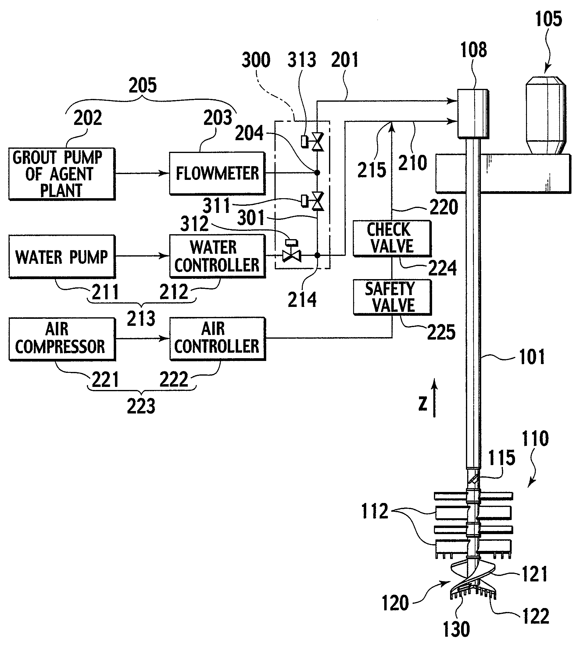
[0073]According to the apparatus of the first modification, stabilizer piping 201 has an air inlet 206. The air inlet 206 is connected to a front end of air piping 220A that is branched from a branch point 226. The branch point 226 is formed in air piping 220 downstream from a check valve 224. This arrangement can introduce compressed air into a stabilizer passed through the stabilizer piping 201. Two valves 227 and 228 are provided for the air piping 220 downstream from the branch point 226, to guide compressed air of the air piping 220 into one of the air inlet 206 of the stabilizer piping 201 and a joint 215 of water piping 210.
[0074]When drilling the ground, the valve 227 is opened and the valve 228 is closed to mix compressed air with pressurized water to form a fluid mixture, which is fed to a drilling head 120, thereby achieving the effect of the above-mention...
second modification
[0076]FIG. 13 shows an apparatus for soil improvement work according to a second modification of the present invention.
[0077]The second modification is basically the same as the first modification of FIG. 12 except that a tank 229 is arranged in piping between an air controller 222 and a check valve 224 and the tank 229 is connected to a safety valve 225.
[0078]Even if water or stabilizer (cement slurry) reversely flows through the check valve 224 toward the air controller 222, the water or stabilizer can be discharged to the outside through the tank 229 and safety valve 225, thereby surely preventing the water or stabilizer from entering the air controller 222.
PUM
 Abstract
Description
Claims
Application Information