Electrical connector with divider shields to minimize crosstalk

a technology of divider shields and electrical connectors, applied in the direction of fixed connections, coupling device details, coupling device connections, etc., can solve the problems of signal reflection, less electrical noise, and relatively high manufacturing costs of connectors, and achieve the effect of reducing crosstalk and low cos

Active Publication Date: 2010-01-26
AMPHENOL CORP
View PDF29 Cites 33 Cited by
  • Summary
  • Abstract
  • Description
  • Claims
  • Application Information

AI Technical Summary

Benefits of technology

[0009]The present invention provides increased metal presence around the contact region of an electrical connector to minimize crosstalk. The present invention also provides a component that can be manufactured separately from the contact region and at low cost.

Problems solved by technology

However, as a result of increasing signal frequencies, the connectors encounter more electrical noise.
Signal reflections are caused by signal path imperfections that give rise to impedance mismatching.
Also, changes in the signal path characteristics, particularly abrupt changes, can cause signals to be reflected.
Also, in a region where the signal path electrically connects to another circuit, manufacturing costs are relatively higher since the signal path must be formed and shaped to provide an acceptable electrical connection that is mechanically durable.
Such connections are typically more difficult to manufacture because a more complicated shape is required and therefore is more costly to form.
However, the use of plastic containing conductive materials between signal paths does not provide the stiffness, the shielding, or the lower relative manufacturing cost of using a metal shield.

Method used


Image

  • Electrical connector with divider shields to minimize crosstalk
  • Electrical connector with divider shields to minimize crosstalk
  • Electrical connector with divider shields to minimize crosstalk

Examples


Embodiment Construction

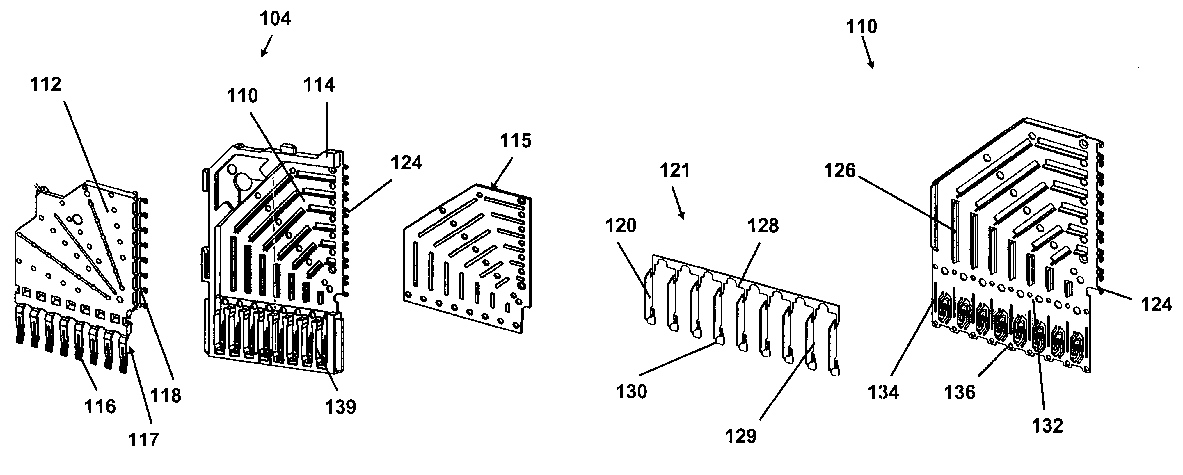
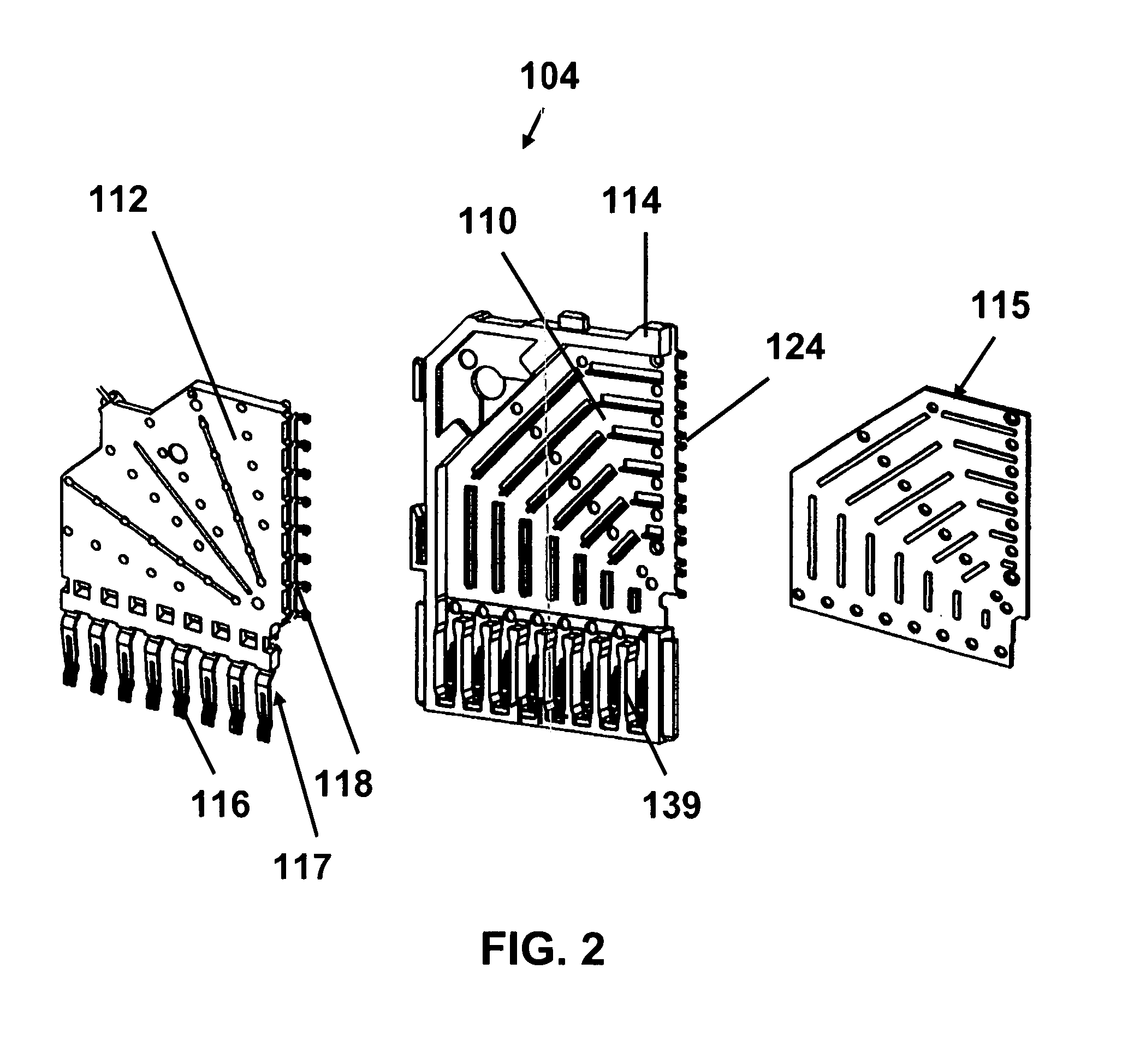
[0024]Referring to FIGS. 1-9, an electrical connector 10 provides improved shielding by increasing the presence of conductive material in the contact region. The improved shielding can be manufactured separately from the contact region and is inexpensive to manufacture.

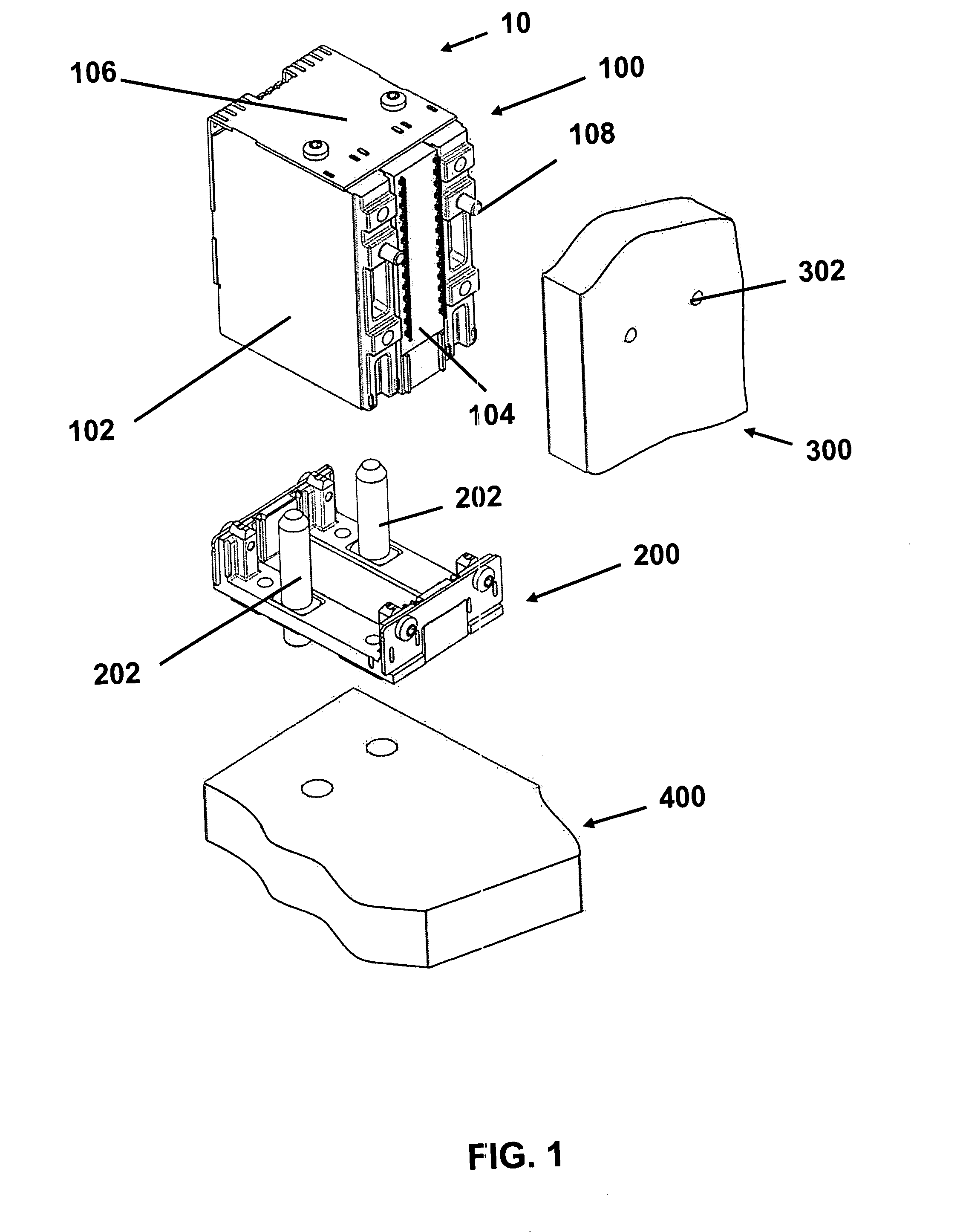
[0025]Referring to FIG. 1, the electrical connector 10 is shown. The electrical connector 10 includes a daughter card connector 100 and a backplane connector 200. The electrical connector 10 provides signal pathways. The daughter card connector 100 is adapted to be mated to the backplane connector 200. In the embodiment shown, the daughter card connector 100 and the backplane connector 200 when mated with each other provide signal pathways for two printed circuit boards 300 and 400 that are at substantially right angles to one another.

[0026]However, the electrical connector 10 of the present invention is not intended to be limited to providing signal pathways to printed circuit boards, two circuits, or printed circuit...


PUM


Abstract

A wafer for an electrical connector includes a conductive shield plate, a plurality of signal conductors disposed on the shield plate, and a divider shield. Each of the plurality of signal conductors has at least one contact portion. The divider shield is disposed on the shield plate aligned with the at least one contact portion and is made of conductive metal. The divider shield is separate from and coupled to the shield plate.

Description

FIELD OF THE INVENTION[0001]The present invention relates generally to electrical interconnection systems. More particularly, the present invention relates to interconnection systems with crosstalk reduction.BACKGROUND OF THE INVENTION[0002]For ease of manufacture and cost effectiveness, an electronic system is generally manufactured on several separate printed circuit boards. These separate printed circuit boards are then connected to one another by electrical connectors. Typically, one printed circuit board serves as a backplane. Other printed circuit boards, often called daughter boards or daughter cards, are then connected to the backplane by electrical connectors as part of the electronic system.[0003]To meet the demand for electronic systems that are more compact, faster, and more complex, increasingly more circuits are placed within a given area of each printed circuit board, and those circuits operate at increasingly higher frequencies. Correspondingly, the electrical connec...

Claims


Application Information

Patent Timeline
Patent Type & Authority Patents(United States)
IPC IPC(8): H01R12/00
CPCH01R13/514H01R23/688H01R12/52H01R13/6587H01R13/6471
Inventor MCNAMARA, DAVID MICHAEL
Owner AMPHENOL CORP
Why Eureka
Try Eureka