Article having display device
a display device and display device technology, applied in the field of ic cards, can solve the problems of easy forgery of the picture of the face, the misapplication of the ic card becomes a bigger problem,
- Summary
- Abstract
- Description
- Claims
- Application Information
AI Technical Summary
Benefits of technology
Problems solved by technology
Method used
Image
Examples
embodiment 1
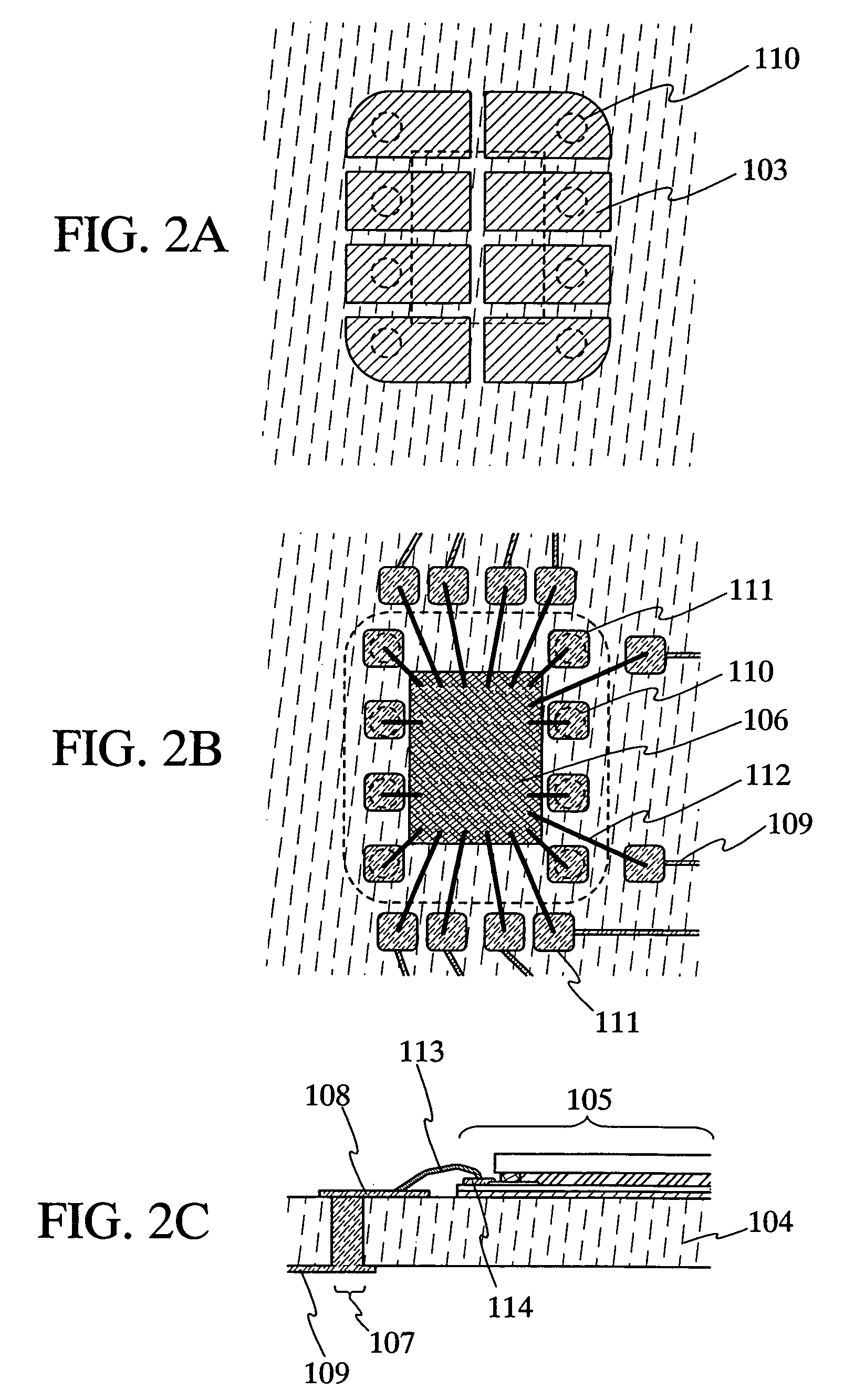
[0134]In this embodiment, electrical connection between an interposer provided for a contact type IC card and a thin film integrated circuit is described.
[0135]FIG. 11A is an oblique perspective figure showing a cross-sectional structure of the thin film integrated circuit connected to the interposer by a wire-bonding method. Reference number 601 denotes an interposer, 602 denotes a thin film integrated circuit. The thin film integrated circuit 602 is mounted over the interposer 601 by an adhesive agent 604 for mounting.
[0136]A connection terminal 605 is provided for a reverse side of the face over which the thin film integrated circuit 602 is mounted in the interposer 601 shown in FIG. 11A. A pad 606 provided for the interposer 601 is electrically connected to the connection terminal 605 via a contact hole provided for the interposer 601.
[0137]In this embodiment, the connection terminal 605 is electrically connected to the pad 606 directly through the contact hole. However, for exa...
embodiment 2
[0145]In this embodiment, a specific example of using an IC card of the present invention as an ATM card is described.
[0146]As shown in FIG. 12, image data of a bank depositor's face is memorized in a ROM provided for a thin film integrated circuit of an ATM card when he / she opens an account in a financial institution such as a bank. Forgery such as changing the photograph of a human face can be prevented by memorizing the data thereof in the ROM. The ATM card is provided for the bank depositor, and then he / she can begin to use the ATM card.
[0147]An ATM card is used for dealings at an ATM (automated teller machine) or a window. When dealing such as withdrawing, depositing, or transferring cash is done, details such as deposit balance or dealing date is required to be memorized in an EEPROM provided for a thin film integrated circuit of an ATM card.
[0148]After the dealing, details such as deposit balance or dealing date may be displayed in a pixel portion of the ATM card, and the dis...
embodiment 3
[0151]In this embodiment, a case in which a plurality of liquid crystal display devices is manufactured from one substrate is described.
[0152]FIG. 13A is a top view of a substrate when a plurality of liquid crystal display devices is manufactured at the same time over a first substrate 1301. A sealing material 1302 to surround an area in which a liquid crystal is to be sealed is laid out and formed over the first substrate 1301 over which an alignment film is formed. A liquid crystal 1303 is dripped to the area surrounded by the sealing material 1302.
[0153]FIG. 13B is a cross sectional view along a broken line A-A′ in FIG. 13A. As shown in FIG. 13B, the liquid crystal 1303 is dripped to the area surrounded by the sealing material 1302. Next, as shown in FIG. 13C, an opposite substrate 1304 is pressure-bonded so that the liquid crystal 1303 can be sealed within the area surrounded by the sealing material 1302.
[0154]After pressure-bonding the opposite substrate, as shown in FIG. 13D, ...
PUM
 Abstract
Description
Claims
Application Information
 - R&D
- Intellectual Property
- Life Sciences
- Materials
- Tech Scout
- Unparalleled Data Quality
- Higher Quality Content
- 60% Fewer Hallucinations
Browse by: Latest US Patents, China's latest patents, Technical Efficacy Thesaurus, Application Domain, Technology Topic, Popular Technical Reports.
© 2025 PatSnap. All rights reserved.Legal|Privacy policy|Modern Slavery Act Transparency Statement|Sitemap|About US| Contact US: help@patsnap.com


