Electronic device, cooling device and loop heat pipe

a technology of electronic devices and loop heat pipes, which is applied in the direction of indirect heat exchangers, lighting and heating devices, instruments, etc., can solve the problems of low heat transport efficiency and lowering the heat transport efficiency

Active Publication Date: 2010-01-26
TOSHIBA CLIENT SOLUTIONS CO LTD
View PDF18 Cites 16 Cited by
  • Summary
  • Abstract
  • Description
  • Claims
  • Application Information

AI Technical Summary

Problems solved by technology

However, the conventional heat pipe described above takes such a structure that vapor bubbles are transported by pressure oscillatory wave, which has a low heat transport efficiency.
With this structure, the heat of the gas phase portion of the working fluid is transmitted to the liquid phase of the liquid, and thus a part of the heat being transported is in some cases returned to the heat receiving portion, thereby lowering the efficiency of the heat transport.

Method used


Image

  • Electronic device, cooling device and loop heat pipe
  • Electronic device, cooling device and loop heat pipe
  • Electronic device, cooling device and loop heat pipe

Examples


first embodiment

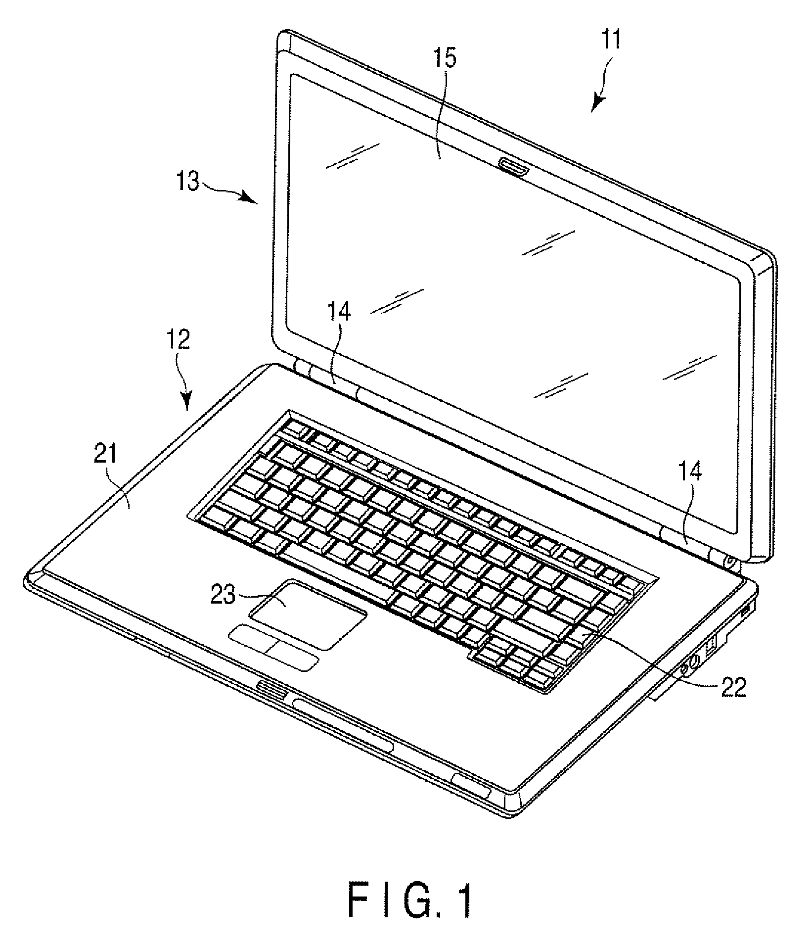
[0017]the electronic device will now be described with reference to FIGS. 1 to 6. As shown in FIG. 1, a portable computer 11, which is an example of the electronic device, includes a main body unit 12, a display unit 13 and a hinge mechanism 14 provided between the main body unit 12 and the display unit 13. The hinge mechanism 14 supports the display unit 13 so as to be pivotable with respect to the main body unit 12.

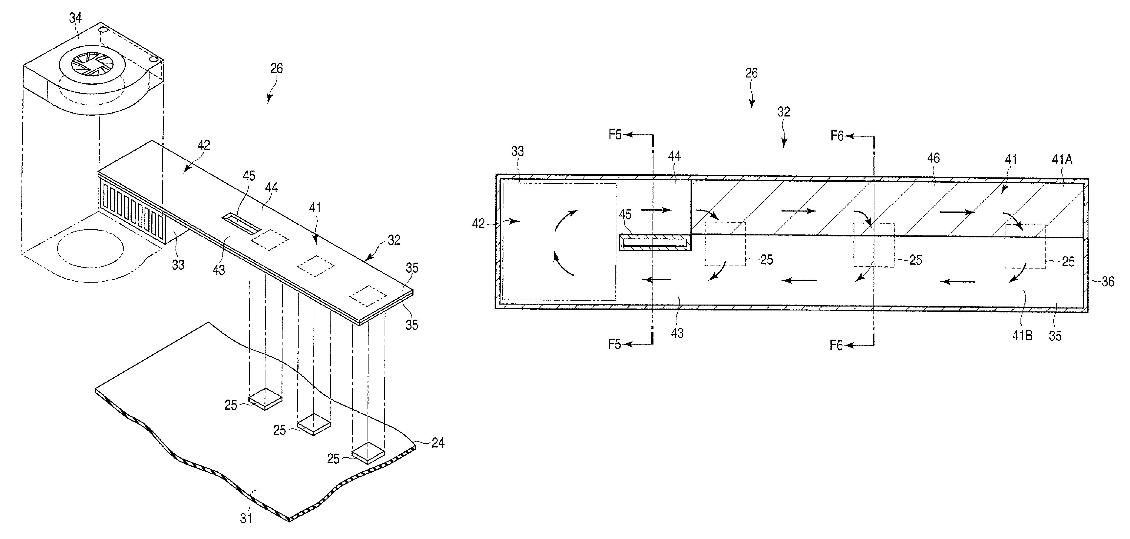
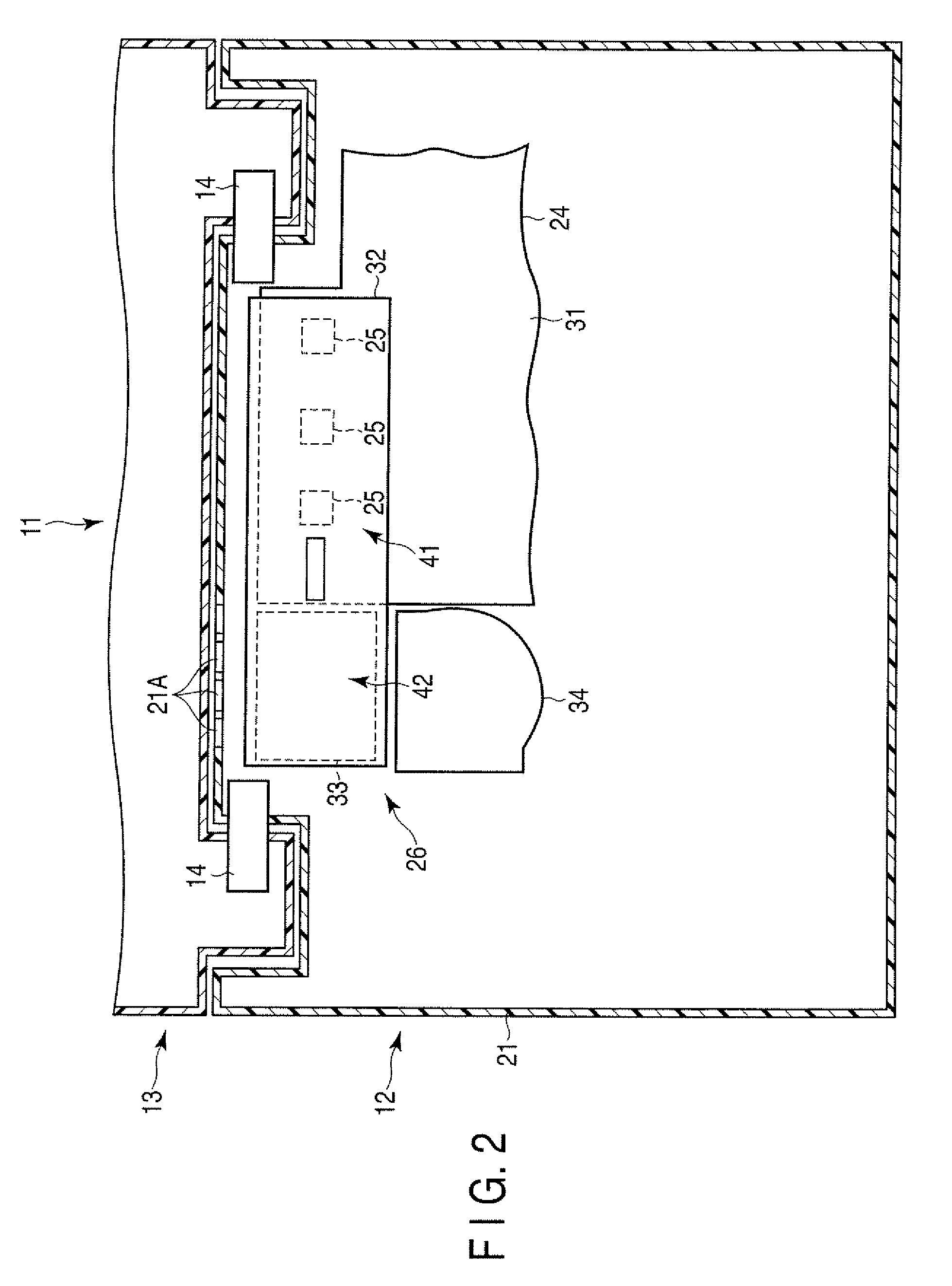
[0018]The display unit 13 includes a display 15. The display 15 is, for example, a liquid crystal display. As can be seen in FIGS. 1 and 2, the main body unit 12 contains a housing 21, a keyboard 22 mounted to the housing 21, a touch pad 23, a printed circuit board 24 housed inside the housing 21, and a cooling device 26 also housed inside the housing 21 in order to cool down heat generating parts 25 of the printed circuit board 24.

[0019]As can be seen in FIGS. 2 and 3, the printed circuit board 24 includes a printed wiring board 31 in which a plurality of copper-made w...

second embodiment

[0039]The wick 52 of the second embodiment is formed of, for example, a porous material prepared by sintering metal powder, more specifically, copper powder to the inner side of the plate member 35. The wick 52 is provided in the first region 41A of the heat receiving portion 41 and the inside of the liquid returning flow path 44. The wick 52 is formed continuously to extend from the first region 41A of the heat receiving portion 41 to the inside of the liquid returning flow path 44.

[0040]According to the second embodiment, the wick 52 is formed to continue as it extends from the first region 41A to the inside of the liquid returning flow path 44. With this structure, the liquefied portion of the working fluid inside the liquid returning flow path 44 can be suctioned even up to the heat receiving portion 41, and therefore the angle dependency of the loop heat pipe 32 can be further decreased. In this manner, it becomes possible to provide the loop heat pipe 32, which is appropriate ...

third embodiment

[0043]The wick 62 of the third embodiment is formed of, for example, a porous material prepared by sintering metal powder, more specifically, copper powder to the inner side of the plate member 35. The wick 62 is provided in the first region 41A of the heat receiving portion 41, the inside of the liquid returning flow path 44 and a section of the inside of the heat radiating portion 42. The wick 62 is formed continuously to extend from the first region 41A of the heat receiving portion 41, passing through the inside of the liquid returning flow path 44, and to the inside of the heat radiating portion 42.

[0044]According to the third embodiment, the wick 62 is formed to continue as it extends from the liquid returning flow path 44 to the inside of the heat radiating portion 42. With this structure, the liquefied portion of the working fluid inside the liquid return flow path 44 can be conveyed in a direction against the gravity and thus the working fluid can be suctioned up to the hea...


PUM


Abstract

According to one embodiment, an electronic device includes a housing, a heat generating part contained in the housing, and a loop heat pipe contained in the housing. The loop heat pipe includes a heat receiving portion, a heat radiating portion, a vapor flow path and a liquid return flow path. The heat receiving portion includes a first region connected to the liquid return flow path and provided with a wick, and a second region formed to be hollow, connected to the vapor flow path. The heat receiving portion is thermally connected to the heat generating part at a position across the first region and the second region.

Description

CROSS-REFERENCE TO RELATED APPLICATIONS[0001]This application is based upon and claims the benefit of priority from Japanese Patent Application No. 2008-083435, filed Mar. 27, 2008, the entire contents of which are incorporated herein by reference.BACKGROUND[0002]1. Field[0003]One embodiment of the present invention relates to an electronic device equipped with a loop heat pipe for cooling a heat generating part, a cooling device and a loop heat pipe.[0004]2. Description of the Related Art[0005]For example, Japanese patent application, Jpn. Pat. Appln. KOKAI Publication No. 11-190596 discloses a loop-shaped flat-type heat pipe having the following structure. This loop heat pipe includes a box-shaped container inside which a groove wick is provided, a recessed wall recessed in the vicinity of a central portion of the container and brought into contact with an opposing wall and a working fluid injected in the container. The recessed wall has a length shorter than an effective length o...

Claims


Application Information

Patent Timeline
Patent Type & Authority Patents(United States)
IPC IPC(8): H05K7/20F28D15/04
CPCF28D15/0266G06F1/203H01L2924/0002H01L2924/00
Inventor TOMIOKA, KENTARO
Owner TOSHIBA CLIENT SOLUTIONS CO LTD
Why Eureka
Try Eureka