Light information apparatus and control method of light information apparatus

a technology of light information apparatus and control method, which is applied in the field of optical information apparatus, can solve the problems of deteriorating reproductive signal quality, spherical aberration, and the possibility of accidentally degrading the recorded information recorded on the optical recording medium, and achieves stable control signal and stable reproductive signal

Inactive Publication Date: 2010-01-26
PANASONIC CORP
View PDF7 Cites 2 Cited by
  • Summary
  • Abstract
  • Description
  • Claims
  • Application Information

AI Technical Summary

Benefits of technology

[0060]Since it becomes possible in the present invention not only to respond to dispersion in thickness of a protective layer of an optical recording medium without depending on optical conditions in a design of an optical head, but also to keep outgoing power of an output to a side of an objective lens constant, it becomes possible to achieve an optical information apparatus which can obtain a stable control signal and a stable reproductive signal regardless of the thickness dispersion of the protective layer of the optical recording medium.
[0061]In addition, it becomes possible in the present invention to achieve an optical information apparatus where stable migration between recording layers becomes possible without a possibility of degrading accidentally the recorded information, recorded on the optical recording medium, being radiated at the power more than needed during reproduction by performing the setting at a spherical aberration correction amount suitable for a recording layer to be newly focused after lowering the outgoing power of an objective lens output beforehand.

Problems solved by technology

However, spherical aberration resulting from an error of thickness of a protective layer protecting a recording layer of an optical recording medium is proportional to the biquadrate of NA.
At this time, while reproducing the optical recording medium 10, power more than needed is irradiated on the optical recording medium 10, and there is a possibility of accidentally degrading recorded information recorded on the optical recording medium 10.
At this time, while reproducing the optical recording medium 10, reproductive signal quality deteriorates, and there is a possibility that it may become impossible to reproduce recording information.
Nevertheless, the former measure imposes severe optical conditions in a design of the optical head 1 to both of designs of sides of the objective lens 9 and optical detector 15, and hence, itself is reflected in manufacturing cost.
Furthermore, optimal size of satisfying both optical conditions is enlarged and when it cannot be obtained within, for example, the designed size of a conventional light head, a malfunction that a new parts design must be performed is caused.
The same problem arises also in the latter.
In addition, the problem mentioned above arises similarly, when correcting a spherical aberration by moving a collimator lens in the direction of the optical axis.

Method used


Image

  • Light information apparatus and control method of light information apparatus
  • Light information apparatus and control method of light information apparatus
  • Light information apparatus and control method of light information apparatus

Examples


embodiment 1

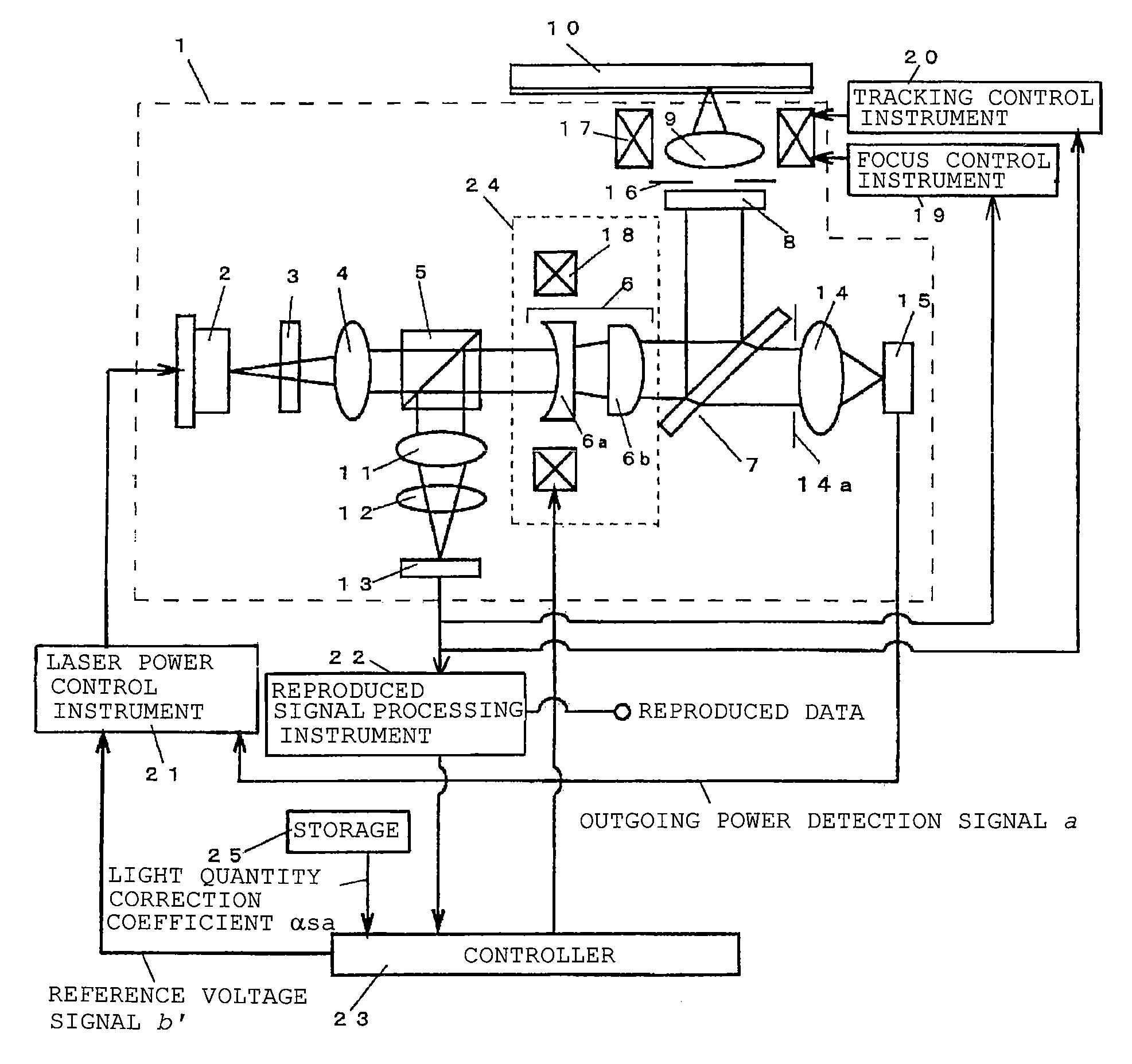
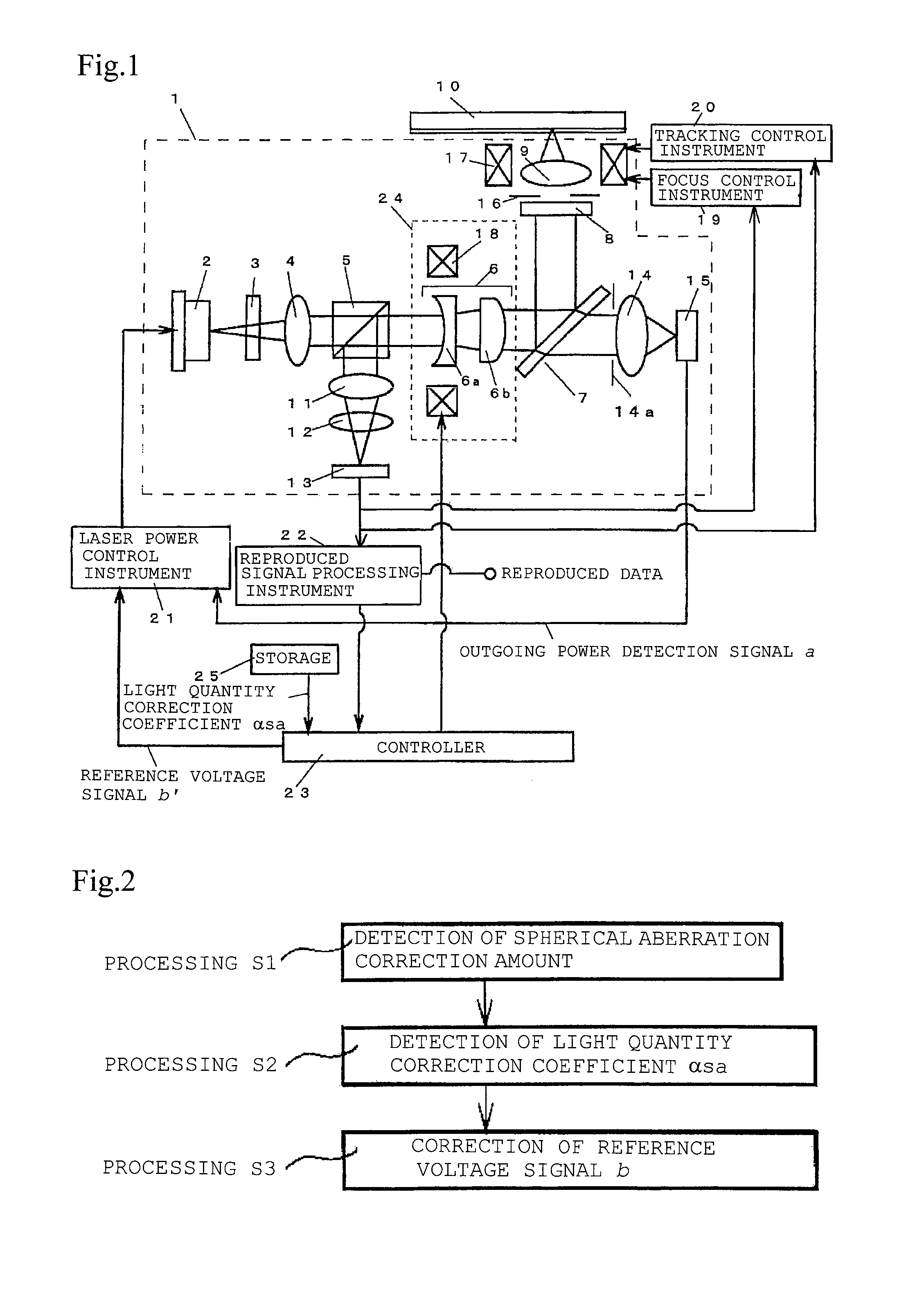
[0120]FIG. 1 is a schematic diagram of an optical information apparatus in a first embodiment. In FIG. 1, the same reference numerals are used for the same constituents as those in FIG. 13, and their detailed description is omitted.

[0121]In FIG. 1, reference numeral 14 denotes a lens which condenses light, permeating the mirror 7, to the light quantity detector 15, reference numeral 15 denotes the light quantity detector which transforms a received light beam into an electric signal, and light quantity detection instrument is constituted of the lens 14 and light quantity detector 15. In addition, reference numeral 22 denotes reproduced signal processing instrument, reference numeral 23 denotes a controller, and reference numeral 25 denotes storage.

[0122]A light beam received by the photodetector 13 is transformed into an electric signal, which is supplied to the focus control instrument 19, tracking control instrument 20, and reproductive signal processing instrument 22.

[0123]A repr...

embodiment 2

[0155]FIG. 8 is a schematic diagram showing structure of an optical information apparatus in a second embodiment. In FIG. 7, the same reference numerals are used for the same constituents as those in FIG. 1 or 13, and their detailed description is omitted. In addition, in FIG. 8, reference numeral 40 denotes an optical recording medium having two layers of recording layers, reference numeral 48 denotes focus control instrument, reference numeral 49 denotes tracking control instrument, and reference numeral 53 denotes a controller.

[0156]FIG. 9 shows an example of a schematic diagram of an optical recording medium having two layers of recording layers. It has constitution of a surface 87, a protective layer 82, a first recording layer 83, an interlayer 85, a second recording layer 84, and a base material 86, which is a back, from an optical head side in order. The protective layer 82 and interlayers 85 are transparent media such as a resin. Since the interlayer 85 is between the first...


PUM

PropertyMeasurementUnit
thicknessaaaaaaaaaa
wavelengthaaaaaaaaaa
poweraaaaaaaaaa

Abstract

An optical information apparatus includes a laser which emits a light beam, an objective lens and the like which converge a light beam emitted from the laser on an optical recording medium, spherical aberration correction instrument which is arranged on an optical axis of the light beam which links the laser and the objective lens, and corrects a spherical aberration generated on the optical recording medium. Correction is performed so that outgoing power of the laser changes according to a correction amount by the spherical aberration correction instrument.

Description

[0001]This application is a U.S. national phase application of PCT International Application PCT / JP2005 / 011296, filed Jun. 20, 2005.TECHNICAL FIELD[0002]The present invention relates to an optical information apparatus which performs write-in and read-out of an information signal to an optical recording medium like an optical disk, a magneto-optical disk, or an optical card, its control method, and the like.BACKGROUND ART[0003]Optical memory technology using an optical recording medium having a pit-like pattern as a high-density and large-capacity memory medium has been practically used while having extended applications such as a digital versatile disk (DVD), a video disk, a document file disk, and further a data file.[0004]In recent years, in order to further highly densify recording density of an optical recording medium, it has been investigated to enlarge numerical aperture (NA) of an objective lens which converges a light beam on an optical recording medium to form a diffracti...

Claims


Application Information

Patent Timeline
Patent Type & Authority Patents(United States)
IPC IPC(8): G11B7/00
CPCG11B7/1263G11B7/13925G11B7/1378
Inventor YASUDA, KATSUHIKOWADA, HIDENORIYAMAMOTO, TAKEHARUMATSUMOTO, TOSHIO
Owner PANASONIC CORP
Why Eureka
Try Eureka