Arrangement for controlling rock drilling

a rock drilling and arrangement technology, applied in the direction of survey, borehole/well accessories, servomotors, etc., can solve the problems of affecting the operation of the rock drilling machine, the operator cannot ensure a good tool life, and the drilling parameters cannot be quickly adjusted to suit the rock. , to achieve the effect of reducing the percussion pressure, avoiding the formation of harmful tensile stresses, and simple arrangemen

Inactive Publication Date: 2010-02-02
SANDVIK MINING & CONSTR OY
View PDF27 Cites 19 Cited by
  • Summary
  • Abstract
  • Description
  • Claims
  • Application Information

AI Technical Summary

Benefits of technology

[0010]An advantage of the invention is that changes in the penetration rate can be sensed in a relative accurate manner by sensing the pressure drop or the pressure differential at two selected points of the hydraulic circuit. Such sensing of the pressure difference is relatively simple to arrange and alternative solutions exist for the implementation thereof. The invention may further include adjusting the percussion pressure automatically in a certain predetermined proportion to the pressure drop induced by the penetration rate. Since the invention includes decreasing the percussion pressure in soft rock, it is possible to avoid the formation of harmful tensile stresses on drilling equipment.
[0011]The idea underlying an embodiment of the invention is that the pressure before the restrictor and after the restrictor is measured by pressure sensors. Measurement data is delivered to a control unit wherein a predetermined control strategy has been determined, the percussion pressure being controlled with respect to the feed rate according to such a strategy. The control unit is arranged to control at least one electrically controlled valve. The control unit can be provided with various different adjustment strategies. In addition, it is relatively easy to change the adjustment strategies later. The control unit may also control a feed pressure according to a predetermined control strategy. It is also possible the control the feed pressure with the restrictor only, without additional control valve.
[0012]The idea underlying an embodiment of the invention is that the control unit comprises a processor, the computer program to be executed therein being configured to decrease the feed pressure and the percussion pressure when the feed rate increases. In this solution, it is very simple and quick to update the control. A new program product provided with a new adjustment strategy may be downloaded into the control unit later.
[0013]The idea underlying an embodiment of the invention is that at least one monitoring valve arranged to automatically decrease the percussion pressure when the feed rate increases is connected to a hydraulic circuit.
[0014]The idea underlying an embodiment of the invention is that the monitoring valve is arranged to control a load-sense valve or directly a load-sense pump of the hydraulic system.
[0015]The idea underlying an embodiment of the invention is that a pressure ratio at which the percussion pressure vary and the feed pressure may vary is substantially constant during the drilling.

Problems solved by technology

When the quality of rock or the drilling characteristics thereof changes rapidly, even a qualified operator cannot adapt the drilling parameters quickly enough to suit the rock.
It is thus obvious that the operator cannot ensure a good tool life if drilling conditions vary rapidly.
Furthermore, it is practically impossible even for a qualified operator to monitor and control the operation of the rock drilling machine during an entire working shift such that the drilling progresses efficiently at every moment, simultaneously taking into account the stresses the tool is subjected to.

Method used


Image

  • Arrangement for controlling rock drilling
  • Arrangement for controlling rock drilling
  • Arrangement for controlling rock drilling

Examples


Embodiment Construction

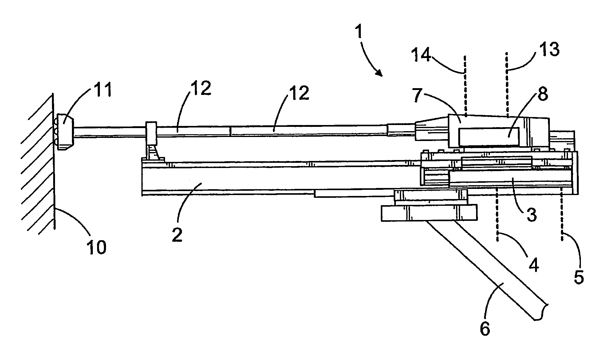
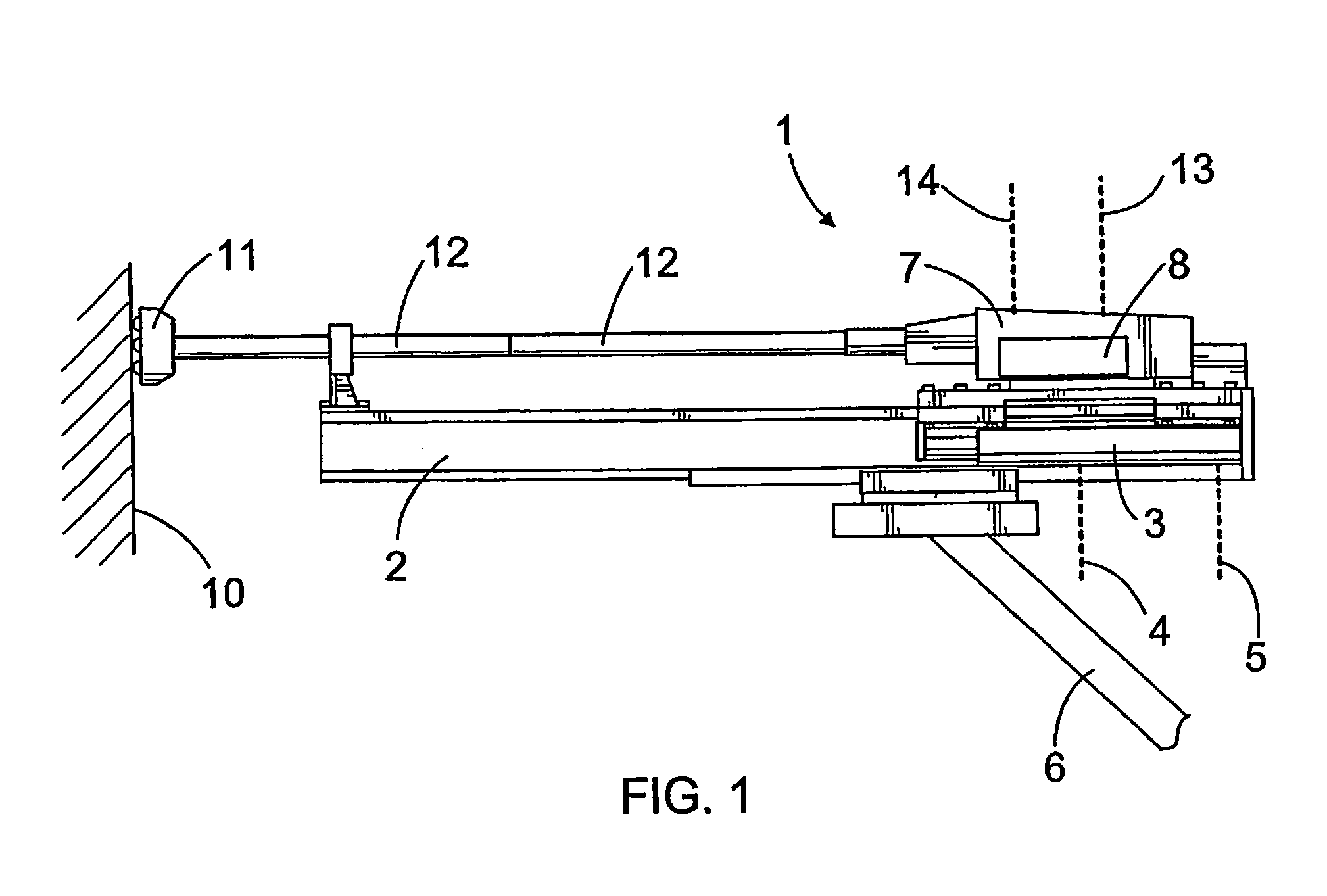
[0023]The rock drilling unit shown in FIG. 1 comprises a rock drill machine 1 arranged on a feed beam 2. The rock drill machine 1 can be moved in the longitudinal direction of the feed beam 2 by means of a feed device 3. The feed actuator 3 is arranged to affect the rock drill machine 1 through a power transmission element, such as a chain or a wire. The feed actuator 3 may be a pressure medium cylinder or a pressure medium motor whereto a pressure medium may be conveyed and wherefrom the pressure medium may be removed along a first channel 4 and a second channel 5, depending on the direction of movement of the feed device 3. The rock drill machine 1 and a tool 9 connected thereto are pressed against rock 10 by using a feed force of a desired magnitude. The feed beam 2 may be movably arranged at a free end of a drilling boom 6 belonging to the rock drilling apparatus. The rock drill machine 1 comprises at least a percussion device 7 and a rotating device 8. The percussion device is ...


PUM


Abstract

A method for controlling rock drilling and a rock drilling arrangement having at least one feed channel of a feed actuator provided with a restrictor, which causes a pressure drop if the penetration rate increases and, consequently, a flow through the restrictor increases. A pressure difference and an increase in the penetration rate can be detected by sensing the pressure before the restrictor and after the restrictor. When the feed rate increases, a hydraulic system is arranged to decrease percussion pressure.

Description

BACKGROUND OF THE INVENTION[0001]The invention relates to a method for controlling rock drilling, wherein a percussion device belonging to a rock drill machine delivers impact pulses to rock through a tool and wherein the rock drill machine is simultaneously pushed against the rock by means of a feed actuator, the method comprising: feeding a pressure medium to the feed actuator along at least one feed channel; feeding the pressure medium to the percussion device along at least one percussion pressure channel; determining a penetration rate; and adjusting at least a percussion pressure on the basis of the penetration rate.[0002]The invention further relates to a rock drilling arrangement comprising: a rock drill machine including a percussion device arranged to generate impact pulses to a tool to be connected to the rock drill machine; a feed beam whereon the rock drill machine has been arranged; a feed actuator enabling the rock drill machine to be moved in the longitudinal directi...

Claims


Application Information

Patent Timeline
Patent Type & Authority Patents(United States)
IPC IPC(8): E21B45/00E21B4/14E21B44/00F15B11/16F15B11/20
CPCE21B44/00F15B11/165F15B11/20F15B2211/20553F15B2211/253F15B2211/30535F15B2211/30545F15B2211/3116F15B2211/3138F15B2211/3144F15B2211/31576F15B2211/327F15B2211/40515F15B2211/50518F15B2211/5157F15B2211/6054F15B2211/6057F15B2211/6313F15B2211/7058F15B2211/78
Inventor NOEL, ROGER
Owner SANDVIK MINING & CONSTR OY
Why Eureka
Try Eureka