Multi-joint drive mechanism and manufacturing method therefor, and grasping hand and robot using those

a technology of driving mechanism and manufacturing method, which is applied in the direction of gripping head, load-engaging elements, program-controlled manipulators, etc., can solve the problems of limiting the use of robot hands, affecting the safety of robot hands, so as to achieve the effect of secure grasping relatively heavyweight objects and controlling the operation of the robot hand

Active Publication Date: 2010-02-02
PANASONIC CORP
View PDF19 Cites 45 Cited by
  • Summary
  • Abstract
  • Description
  • Claims
  • Application Information

AI Technical Summary

Benefits of technology

[0008]An object of the present invention is to provide a multi-joint drive mechanism which can solve the above issues and which has a concrete structure of practicable level including a simplicity of its manufacture as a drive mechanism, and also to provide a manufacturing method for the drive mechanism as well as a grasping hand and a robot using the mechanism.

Problems solved by technology

The robot hand, which has been commercially available for research use, is expensive and restrictive of its use because of its being an assembly of many components.
This actuator, while movably operable softly in every direction, yet has difficulties in securely grasping relatively heavyweight articles and in control of its grasping operations because of its having no skeletal structure.

Method used


Image

  • Multi-joint drive mechanism and manufacturing method therefor, and grasping hand and robot using those
  • Multi-joint drive mechanism and manufacturing method therefor, and grasping hand and robot using those
  • Multi-joint drive mechanism and manufacturing method therefor, and grasping hand and robot using those

Examples


first embodiment

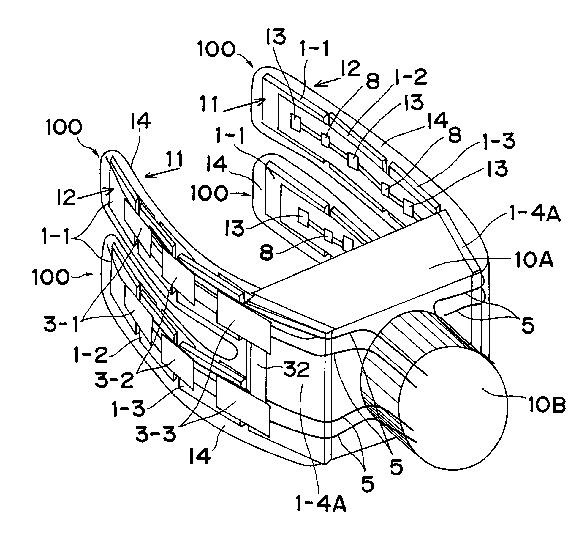
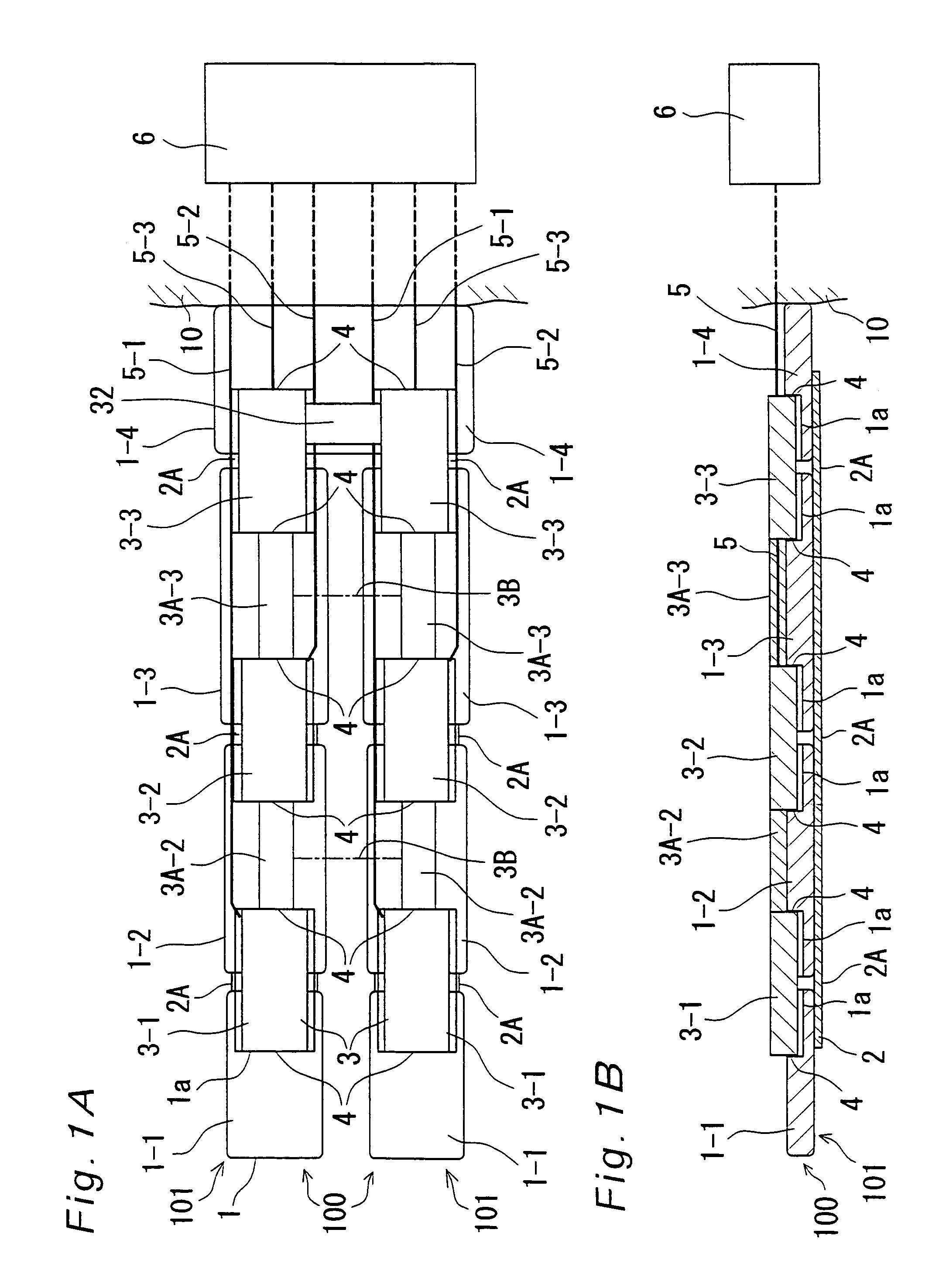
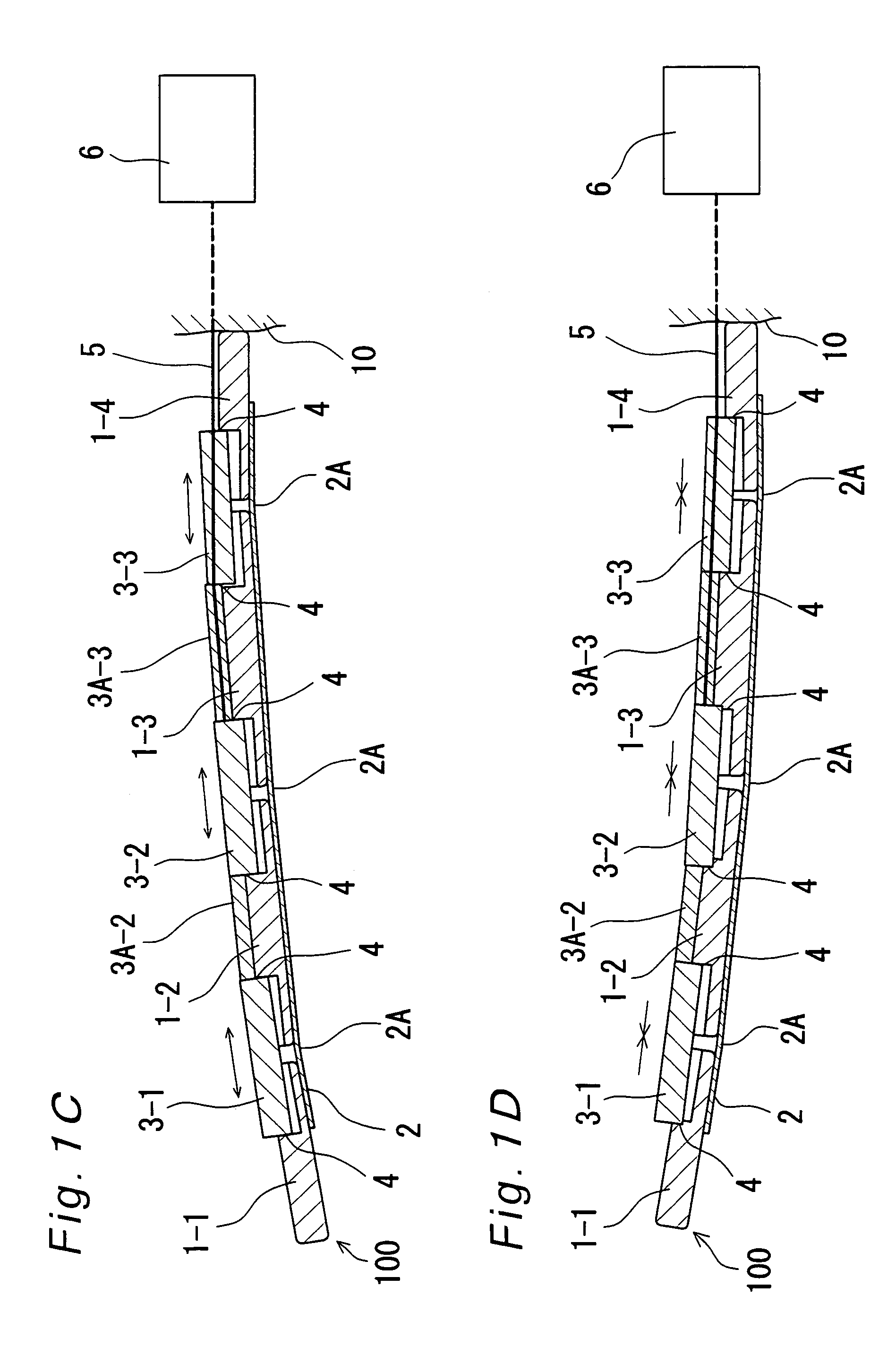
[0075]FIGS. 1A and 1B are a plan view and a sectional view, respectively, of planar-type (flat plane-type in this case) joint drive mechanisms 100, 100 in a first embodiment of the present invention. The joint drive mechanisms 100, 100 shown in FIGS. 1A to 1D are driven by a driving source which is a pneumatic actuator that expands with air pressure applied thereto.

[0076]In FIGS. 1A and 1B, a plurality of bone members 1, e.g. four rectangular-plate-shaped bone members 1 (reference numerals 1-1, 1-2, 1-3, 1-4 are used when places are specifically designated, and reference numeral 1 is generically used when not) are coupled to each other by one elongated rectangular-plate-shaped coupling member 2, where respective adjoining bone members 1 and 1 are made movable relative to each other by respective coupling portions 2A of the coupling member 2 (i.e., portions that function as joints of the multi-joint drive mechanism 100), and where elastic expansion / contraction members 3 (reference nu...

second embodiment

[0090]FIGS. 2A and 2B are a plan view and a sectional view, respectively, of a planar-type joint drive mechanism in a second embodiment of the present invention. The planar-type joint drive mechanism is one in which the joint drive mechanism 100 described in the first embodiment is additionally provided with a sensing function. FIGS. 2A and 2B represent only one array of the joint drive mechanism 100 composed of arrayed bone members 1-1, 1-2, 1-3, 1-4, but the joint drive mechanism 100 may be provided in two arrays like FIG. 1, and otherwise may be provided in multiple arrays. Further, FIGS. 2C and 2D show states in which the individual joint drive mechanisms 100 are deformed by expanding or contracting the elastically expanding / contracting members 3-1, 3-2, 3-3. Furthermore, FIGS. 3A and 3B represent perspective views of grasping hands using this planar-type joint drive mechanism 100 in quantities of four and six, respectively. The elastically expanding / contracting members 3-1, 3-2...

third embodiment

[0111]FIGS. 5A, 5B, and 5C show drive mechanisms in which a rotational degree of freedom of two or three axes is implemented in a planar fashion by an elastic hinge structure using a flat spring. Coupling portions of the bone members 1, each of which is formed into such a shape as to become a butting portion 1B whose width gradually decreases, are coupled together by a flat spring 30 made of rubber having a proper rigidity. This structure provides a universal joint mechanism capable of rotating about the X, Y, and Z axes. When a material having sufficiently large rigidity of the flat spring 30 is selected, the in-plane rigidity of the flat spring 30 is larger than its flexural rigidity and torsional rigidity, and thus, it is also possible to restrain the degree of freedom for rotation about the Z axis. As shown in FIGS. 5B and 5C, strip-shaped elongate elastically expanding / contracting members 31 of the same structure as the elastic expanding / contracting members 3 (e.g., pneumatic a...


PUM


Abstract

A multi-joint drive mechanism includes a bone-member layer member (101) in which a plurality of bone members are arranged in arrays and in a generally planar fashion, the plurality of bone members being movably coupled at coupling portions (3A), and elastically expanding / contracting members (3) which are arranged so as to stretch over the coupling portions on one side or both sides of the bone-member layer member and moreover which are fixed between the plurality of bone members, wherein the multi-joint drive mechanism drives flexural motions of joints between the plurality of adjoining bone members by expanding or contracting the elastically expanding / contracting member.

Description

[0001]This application is the U.S. National Stage application of PCT / JP03 / 07914, filed on Jun. 23, 2003, and claims priority to Japanese Application No. 2002-182504, filed on Jun. 24, 2002.TECHNICAL FIELD[0002]The present invention relates to a multi-joint drive mechanism and a manufacturing method therefor, and a grasping hand and robot using the mechanism. In particular, the present invention relates to a multi-joint drive mechanism, as well as a manufacturing method therefor, capable of grasping various object articles and being simple in structure and low in manufacturing cost, and also relates to a grasping hand and robot using the mechanism.BACKGROUND ART[0003]The grasping hands in conventional industrial robots have hitherto been proposed in many cases as those for use in in-plant production of products and for precision handling of particular components. On the other hand, the grasping hands for robots that are expected to play active part in household chore support or work ...

Claims


Application Information

Patent Timeline
Patent Type & Authority Patents(United States)
IPC IPC(8): B25J15/12B25J9/14B25J15/10
CPCB25J9/142B25J15/10
Inventor YOKOYAMA, KAZUOONO, ATSUSHIASAI, KATSUHIKOADACHI, YUJIYAMAMOTO, MASAKI
Owner PANASONIC CORP
Why Eureka
Try Eureka