Self-contained hydraulic thruster for vessel

a self-contained, hydraulic technology, applied in the direction of motor-driven power plants, special-purpose vessels, vessel construction, etc., can solve the problems of insufficient reinforcement at the lower unit tilt actuator attach point, insufficient power supply of the thruster's single lower unit propeller, and inability to provide marine thrusters, etc., to facilitate hydraulic fluid flow, facilitate the effect of hydraulic fluid flow and greater til

Active Publication Date: 2010-02-02
HYDRAULIC MARINE SYST
View PDF13 Cites 8 Cited by
  • Summary
  • Abstract
  • Description
  • Claims
  • Application Information

AI Technical Summary

Benefits of technology

[0010]It is an object of the present invention to provide a self-contained hydraulic thruster for vessel with an elevated hydraulic fluid reservoir. Design features allowing this object to be accomplished include a hydraulic fluid reservoir mounted on a helm platform which is elevated a substantial height above a base to which a hydraulic power pack is mounted. Benefits associated with the accomplishment of this object include power pack self-priming, and facilitated hydraulic fluid flow from the hydraulic fluid reservoir to the hydraulic power pack.
[0011]It is another object of the present invention to provide a self-contained hydraulic thruster for vessel whose lower unit(s) may be retracted and tilted up without interference from the helm platform. Design features allowing this object to be accomplished include at least one lower unit mounted at an end of a lower unit mounting tube, the lower unit being laterally offset from a steering platform. Advantages associated with the accomplishment of this object include more efficient lower unit stowing for storage and/or transportation, greater tilt achievable (close to 90 degrees), the ability to tilt the propellers and lower unit completely out of the water for servicing and cleaning, decreased corrosion due to the ability of getting the lower units and propellers completely out of the water when not in use to reduce corrosion, and greater retraction of the lower unit.
[0012]It is still another object of this invention to provide a self-contained hydraulic thruster for vessel whose lower units pivot smoothly and easily within respective lower unit bores in lower unit housings. Design features enabling the accomplishment of this object include at least one bushing inside a lower unit bore, and a lower unit bushing bore sized to ...

Problems solved by technology

There are a number of problems associated with currently available marine thrusters.
Another problem with existing designs: the hydraulic fluid reservoir is disposed on the base of the marine thruster, where it is incapable of supplying enough fluid head to self-prime the power pack, and to facilitate hydraulic fluid flow to the hydraulic power pack.
Still another problem is where a marine thruster's single lower unit propeller does not supply enough power to adequately pr...

Method used


Image

  • Self-contained hydraulic thruster for vessel
  • Self-contained hydraulic thruster for vessel
  • Self-contained hydraulic thruster for vessel

Examples


Embodiment Construction

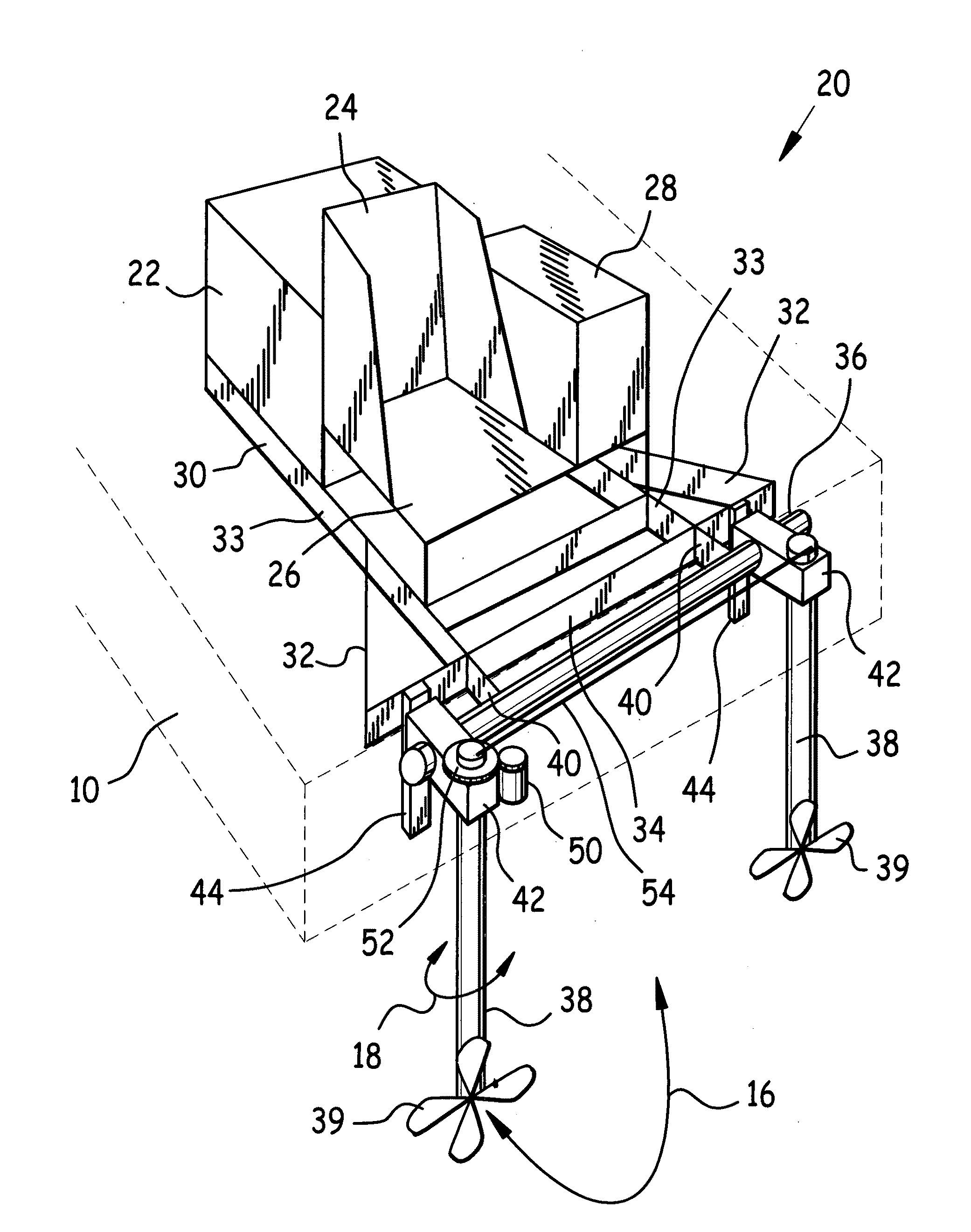
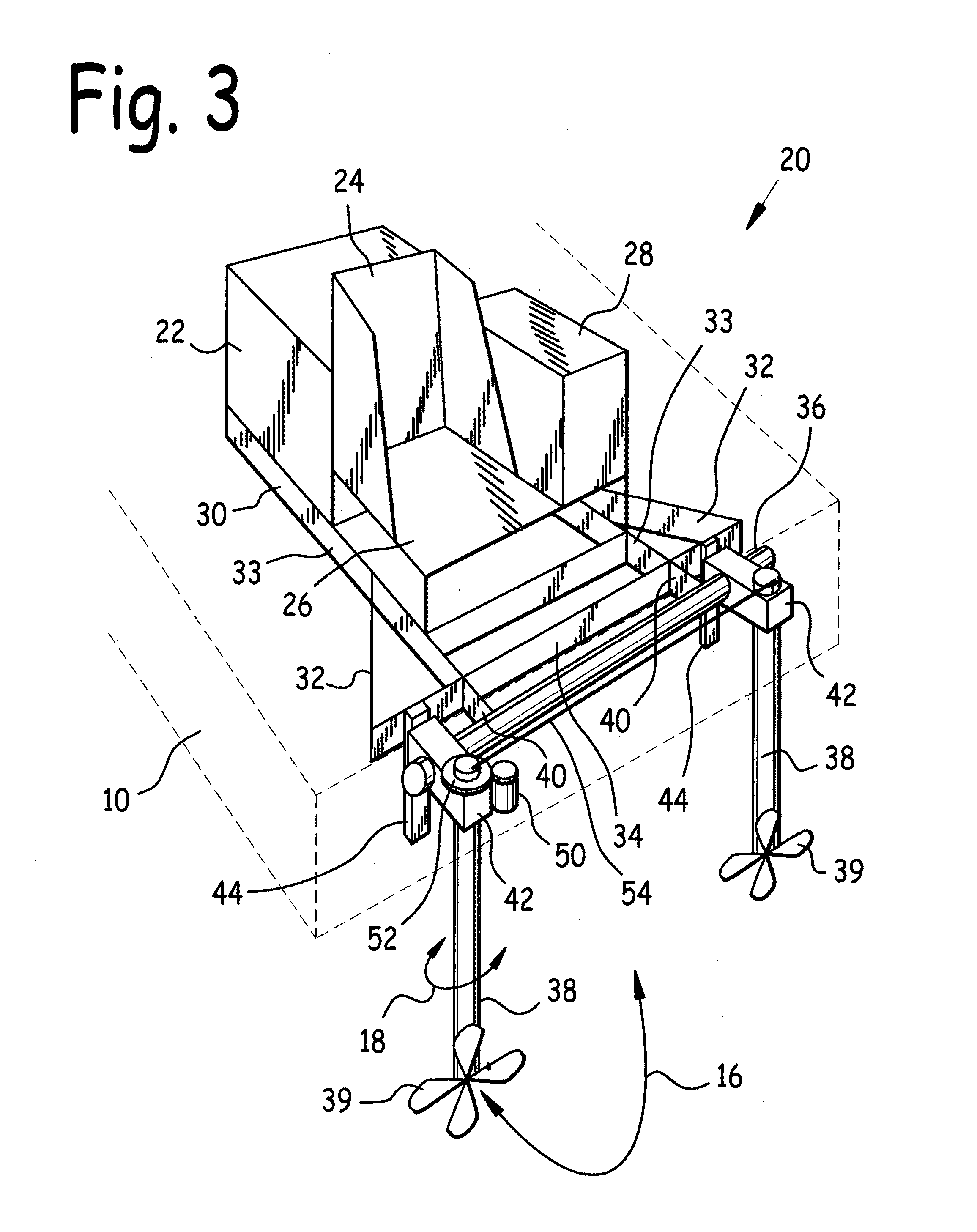
[0029]FIG. 3 is a rear quarter isometric view of self-contained hydraulic thruster 20. Hydraulic thruster 20 comprises base 30 which supports hydraulic power pack 22 and helm platform 26. Helm platform 26 in turn supports helm 24 and hydraulic fluid reservoir 28. Helm platform 26 is elevated above base 30 to elevate hydraulic fluid reservoir 28 above the level of hydraulic power pack 22, and for enhanced visibility for the vessel operator.

[0030]It is desirable to locate hydraulic fluid reservoir 28 above the level of hydraulic power pack 22 to render the hydraulic system self-priming, and to facilitate the flow of hydraulic fluid from hydraulic fluid reservoir 28 to the hydraulic fluid pump in hydraulic power pack 22. Hydraulic power pack 22 is a conventional, commercially available prime mover, such as a diesel engine, coupled to a hydraulic fluid pump, which supplies hydraulic fluid under pressure to power hydraulic thruster 20.

[0031]Base 30 may comprise one or more base feet 32 a...


PUM


Abstract

A self-contained hydraulic thruster for vessel. The hydraulic thruster incorporates an elevated helm platform mounted to a base having reinforced base feet, and a hydraulic fluid reservoir mounted on the helm platform. The elevation of the hydraulic fluid reservoir facilitates flow of hydraulic fluid to a hydraulic power pack mounted on the base. A lower unit mounting tube is attached to the base, and at least one lower unit is mounted at an end of the lower unit mounting tube, laterally offset from the helm platform, so that when the lower unit is retracted and tilted up, it lies on one side of the platform, and the platform doesn't interfere with retraction and tilting of the lower unit. Lower units are pivotably mounted in lower unit housings with lower unit bushings, and steering is provided by a steering motor through an overhung load adaptor to a drive gear.

Description

CLAIM FOR PRIORITY[0001]This utility patent application is based upon and claims the benefit of the earlier filing date of U.S. provisional patent application Ser. No. 60 / 903,400 filed Feb. 26, 2007 entitled Self-Contained Hydraulic Thruster for Vessel.BACKGROUND OF THE INVENTIONField of the Invention[0002]This invention relates to vessel propulsion systems, and in particular to a self-contained hydraulic thruster for vessel.Background of the Invention[0003]Marine thrusters typically mount on barges and flat boats, and are used as propulsion for these vessels. One type of marine thruster employs a prime mover such as a diesel engine driving a hydraulic pump, together known as a “power pack”, and the resultant pressurized hydraulic fluid may be employed to drive a propeller attached to a lower unit.[0004]There are a number of problems associated with currently available marine thrusters. Where a centrally located tiltable lower unit has been retracted and tilted backwards for storage...

Claims


Application Information

Patent Timeline
IPC IPC(8): B63H21/12
CPCB63H23/26
Inventor WILLIAMS, JOHN T.
Owner HYDRAULIC MARINE SYST
Why Eureka
Try Eureka