Sustained delivery of an active agent using an implantable system

Inactive Publication Date: 2010-02-02
INTARCIA THERAPEUTICS INC
View PDF59 Cites 48 Cited by
  • Summary
  • Abstract
  • Description
  • Claims
  • Application Information

AI Technical Summary

Benefits of technology

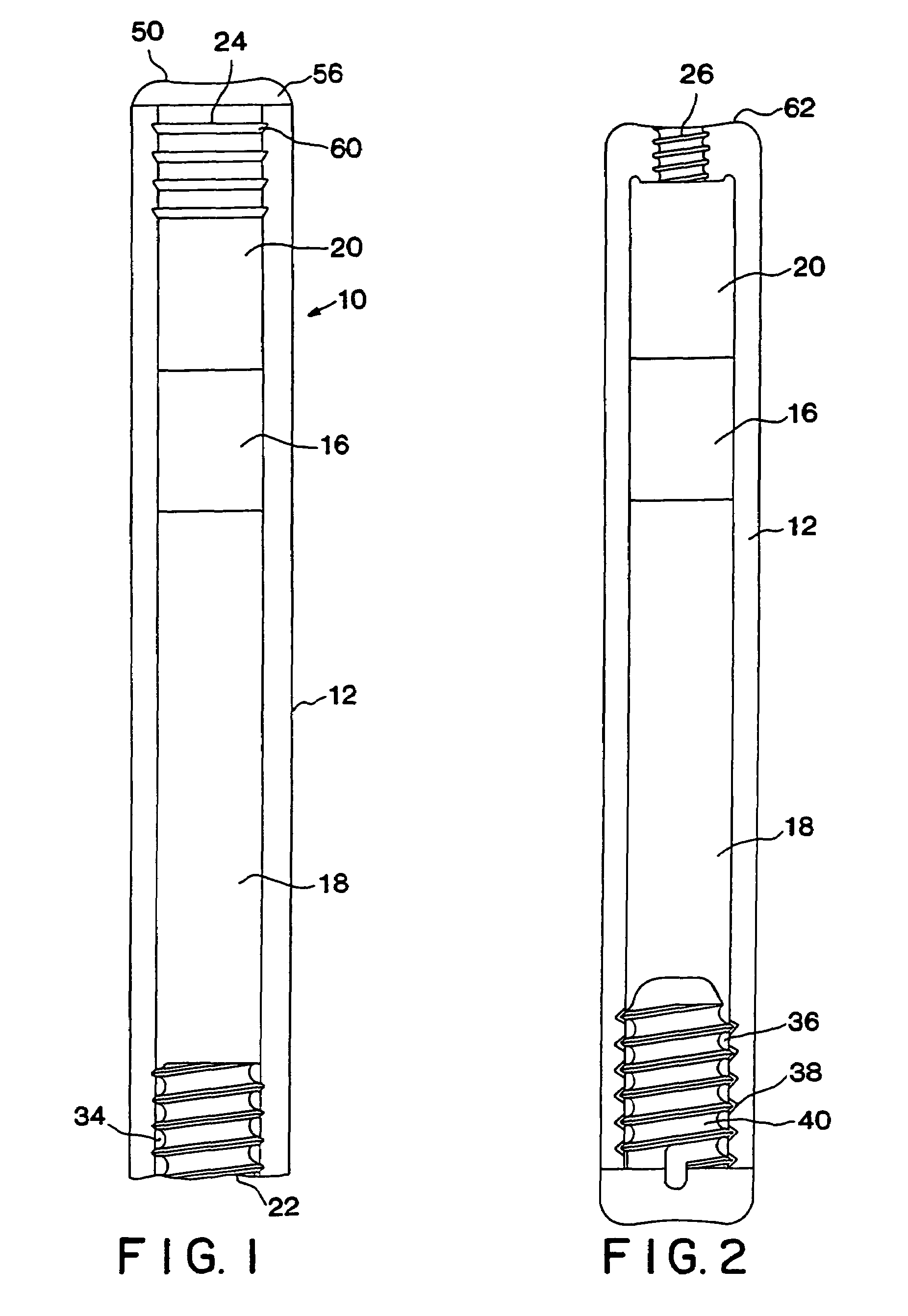
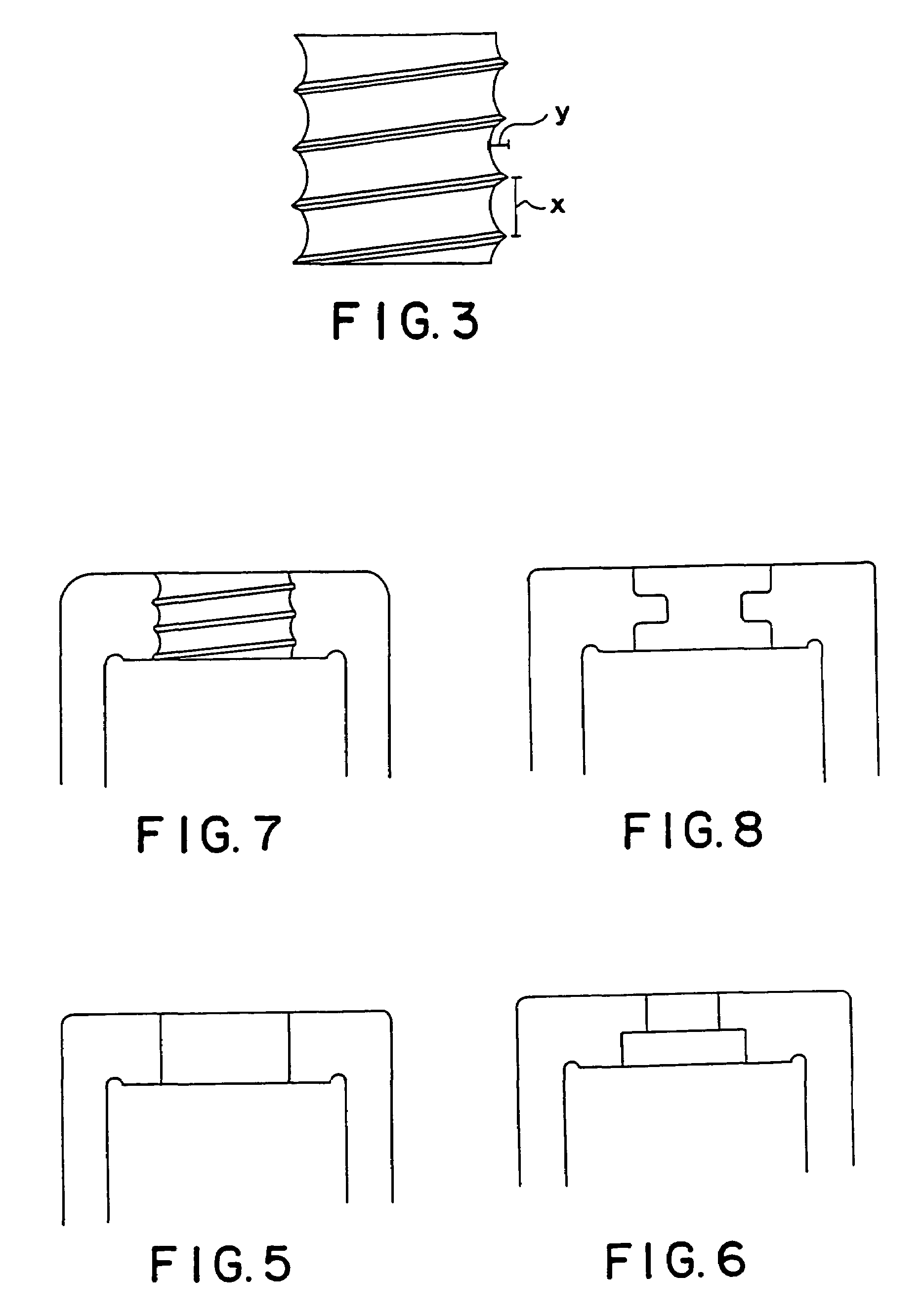
[0015]In still another aspect, the invention is directed to an impermeable active agent delivery system for delivering an active agent that is susceptible to degradation. The reservoir contains a piston that divides the reservoir into a water-swellable agent chamber and an active agent chamber. The open end of the water-swellable agent chamber contains a semipermeable membrane and the open end of the active agent chamber contains a back-diffusion regulating outlet. The system effectively seals the active agent chamber and isolates it from the environment of use.

Problems solved by technology

Adaptation of these systems for human use raises a number of difficult issues.

Method used


Image

  • Sustained delivery of an active agent using an implantable system
  • Sustained delivery of an active agent using an implantable system
  • Sustained delivery of an active agent using an implantable system

Examples


example 1

Preparation of a Device with an HDPE Reservoir

[0090]A system containing leuprolide acetate for the treatment of prostate cancer was assembled from the following components:[0091]Reservoir (HDPE) (5 mm outside diameter, 3 mm inside diameter)[0092]Piston (Santoprene®)[0093]Lubricant (silicone medical fluid)[0094]Compressed osmotic engine (60% NaCl, 40% sodium carboxymethyl cellulose)[0095]Membrane plug (Hytrel® polyether-ester block copolymer, injection molded to desired shape)[0096]Back diffusion regulating outlet (polycarbonate)[0097]Active agent (0.78 g of 60% propylene glycol and 40% leuprolide acetate)

Assembly

[0098]The piston 16 and inner diameter of the reservoir 12 were lightly lubricated with silicon medical fluid. The piston 16 was inserted into the open end of second chamber 20. Two osmotic engine tablets (40 mg each) were then inserted on top of piston 16. After insertion, the osmotic engine was flush with the end of the reservoir 12. The membrane plug 24 was inserted by li...

example 2

Insertion of the Device of Example 1

[0099]Insertion of the device of Example 1 is done under aseptic conditions using a trocar similar to that used in the implantation of Norplant® contraceptive implants to position the device under the skin. The insertion area is typically in the inside of the upper arm, 8 to 10 cm above the elbow.

[0100]The area is anesthetized and an incision is made through the skin. The incision is approximately 4 mm long. The trocar is inserted into the incision until the tip of the trocar is at a distance of 4 to 6 cm from the incision. The obturator is then removed from the trocar and the device of Example 1 inserted into the trocar. The device is then advanced to the open end of the trocar using the obturator. The obturator is then held in position, thus immobilizing the device of Example 1 while the trocar is withdrawn over both the device and the obturator. The obturator is then removed, leaving the implant behind in a well-controlled position. The edges o...

example 3

Removal of the Device of Example 1

[0101]The device of Example 1 is removed as follows: The device is located by fingertip palpation of the upper arm area. The area at one end of the implant is then anesthetized and an approximately 4 mm, perpendicular incision is made through the skin and any fibrous capsule tissue surrounding the implant area. The end of the device opposite the incision is pushed so that the device end proximal to the incision is urged out of the incision. Any further fibrotic tissue is cut with a scalpel. Following removal, the procedure of Example 2 can be followed to insert a new device.


PUM

PropertyMeasurementUnit
lengthaaaaaaaaaa
diameteraaaaaaaaaa
temperatureaaaaaaaaaa

Abstract

The invention is directed to a device for delivering an active agent formulation for a predetermined administration period. An impermeable reservoir is divided into a water-swellable agent chamber and an active agent formulation chamber. Fluid from the environment is imbibed through a semipermeable plug into the water-swellable agent chamber and the active agent formulation is released through a back-diffusion regulating outlet. Delivery periods of up to 2 years are achieved.

Description

CROSS-REFERENCE TO RELATED APPLICATIONS[0001]This application is a continuation of application Ser. No. 10 / 108,303 filed Mar. 28, 2002, now U.S. Pat. No. 6,635,268 B2, which is a continuation of application Ser. No. 09 / 848,211 filed on May 4, 2001, now U.S. Pat. No. 6,395,292 B2, issued May 28, 2002, which is a continuation of application Ser. No. 09 / 366,746 filed on Aug. 4, 1999, now U.S. Pat. No. 6,261,584 B1, issued Jul. 17, 2001, which is a continuation of application Ser. No. 08 / 943,007, filed Oct. 2, 1997, now U.S. Pat. No. 5,985,305, issued Nov. 16, 1999, which is a continuation of application Ser. No. 08 / 791,699 filed on Jan. 30, 1997, now U.S. Pat. No. 5,728,396, issued Mar. 17, 1998, which is a continuation-in-part application of a provisional application Ser. No. 60 / 122,056, which was filed on Feb. 2, 1996 as regular U.S. application Ser. No. 08 / 595,761 and converted to a provisional application via a petition filed on Jan. 21, 1997.TECHNICAL FIELD[0002]This invention is ...

Claims


Application Information

Patent Timeline
Patent Type & Authority Patents(United States)
IPC IPC(8): A61K9/20A61K9/22A61K9/24A61K9/00A61K38/09A61M5/145
CPCA61M5/14526A61K9/0024A61K9/0004A61K38/09A61M2005/14513A61M2206/10Y10T29/49826
Inventor PEERY, JOHN R.DIONNE, KEITH E.ECKENHOFF, JAMES B.ECKENHOFF, LEGAL REPRESENTATIVE, BONNIE J.LANDRAU, FELIX A.LAUTENBACH, SCOTT D.MAGRUDER, JUDY A.WRIGHT, JEREMY C.
Owner INTARCIA THERAPEUTICS INC
Why Eureka
Try Eureka