Device for advancing drillings in the ground

a technology for drilling and drilling holes, applied in drilling rods, drilling pipes, cutting machines, etc., can solve the problems of high torque, difficulty in advancing drilling, and difficulty in achieving good drilling performance in loamy or loose soils, etc., and achieve the effect of increasing the duration of use and reducing the operating cost of the devi

Inactive Publication Date: 2010-02-09
AKER WIRTH
View PDF20 Cites 3 Cited by
  • Summary
  • Abstract
  • Description
  • Claims
  • Application Information

AI Technical Summary

Benefits of technology

[0011]In a first aspect, the invention is therefore based on the object of improving a device disclosed in DE 43 32 113 A 1 in such a way as to make it suitable for a larger range of different soils. In a second aspect, the device is intended to be developed in such a way that the operating costs associated with its use are reduced. In a third aspect, the duration of use of the device is to be increased. Finally, in a fourth aspect, the drilled material is to be transported reliably away from the drill head space. It goes without saying that the various aspects can also advantageously be realized together in one device.

Problems solved by technology

Difficulties thus frequently arise when the nature of the soil to be removed varies over the length of the drill, For instance, rock drill heads generally equipped with rollers, bits or disks become stuck in soft, for example loamy, soils; by contrast, drill heads displaying good drilling performances in loamy or loose soils rapidly fail “due to high wear on encountering rock or large stones.
In the device disclosed in DE 43 32113 A1, this problem is to be solved by the drill head being caused to make a wobbling movement, with the result that it executes rapid percussive movements with high frequency and, accordingly, with high kinetic energy against the rock face or borehole bottom, yet simultaneously clears the detached drilled material with a high degree of torque and at a low speed, or, if the soil at the rock face is too soft for spalling, peels off soil with a high degree of torque.
Although the device disclosed in DE 43 32 113 A 1 has been shown to be suitable for loosening soil having a high degree of variation, a disadvantage is that the rotational speed of the drill head is not optimal for many soil conditions, since it is usually too high.
A further disadvantage is that the drill head subjected to a significant degree of wear due to the drilling process is expensive and complicated to manufacture on account of the external bevel wheel, resulting in an increase in the running operating costs of this device.
An additional disadvantage is the fact that the bevel wheels running on one another are subjected to an increased degree of wear as a result of penetrating waste.
A final disadvantage is the fact that large pieces of drilled material in particular are not transported away reliably and the conveying line tends to clog up.

Method used


Image

  • Device for advancing drillings in the ground
  • Device for advancing drillings in the ground
  • Device for advancing drillings in the ground

Examples


Embodiment Construction

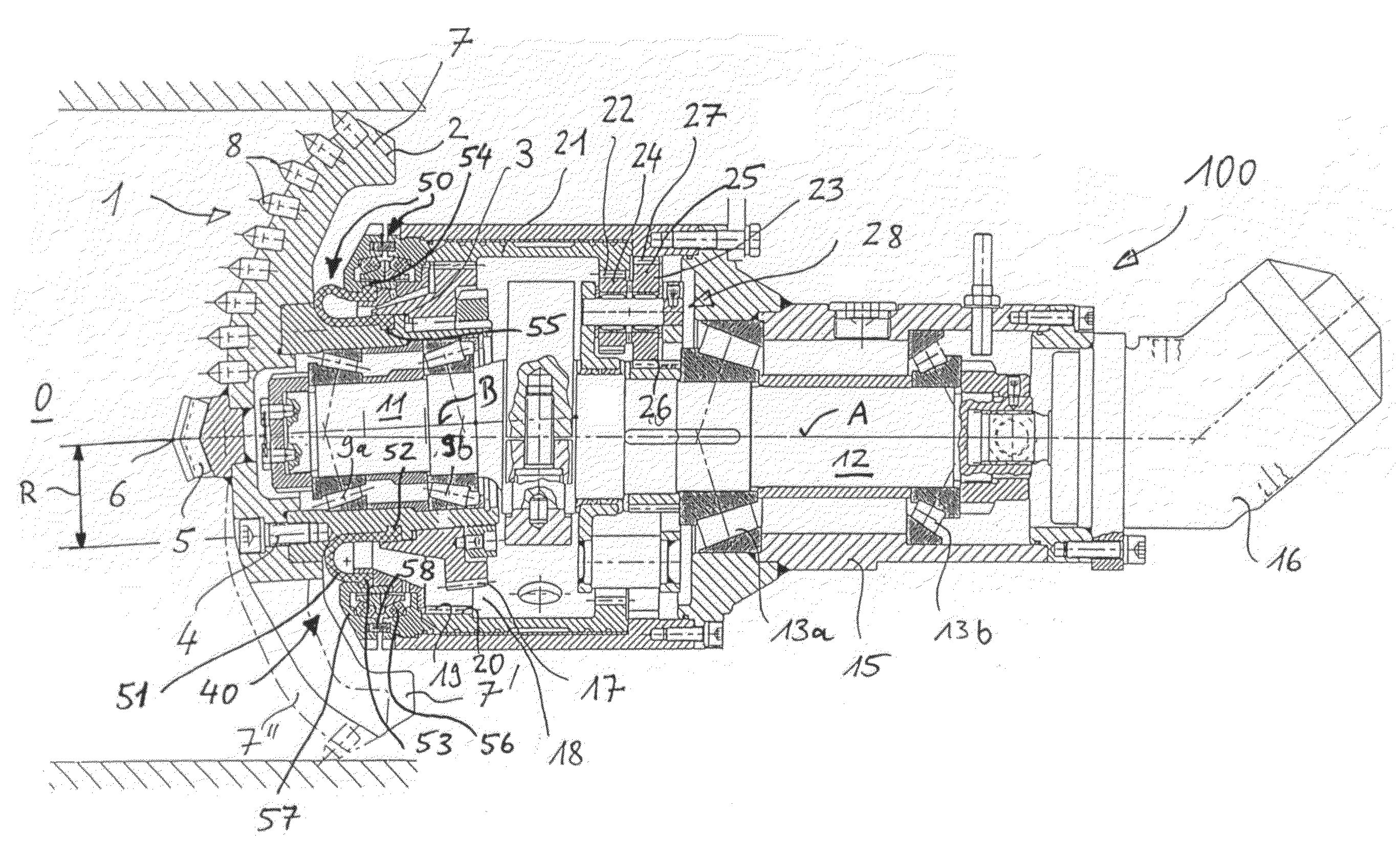
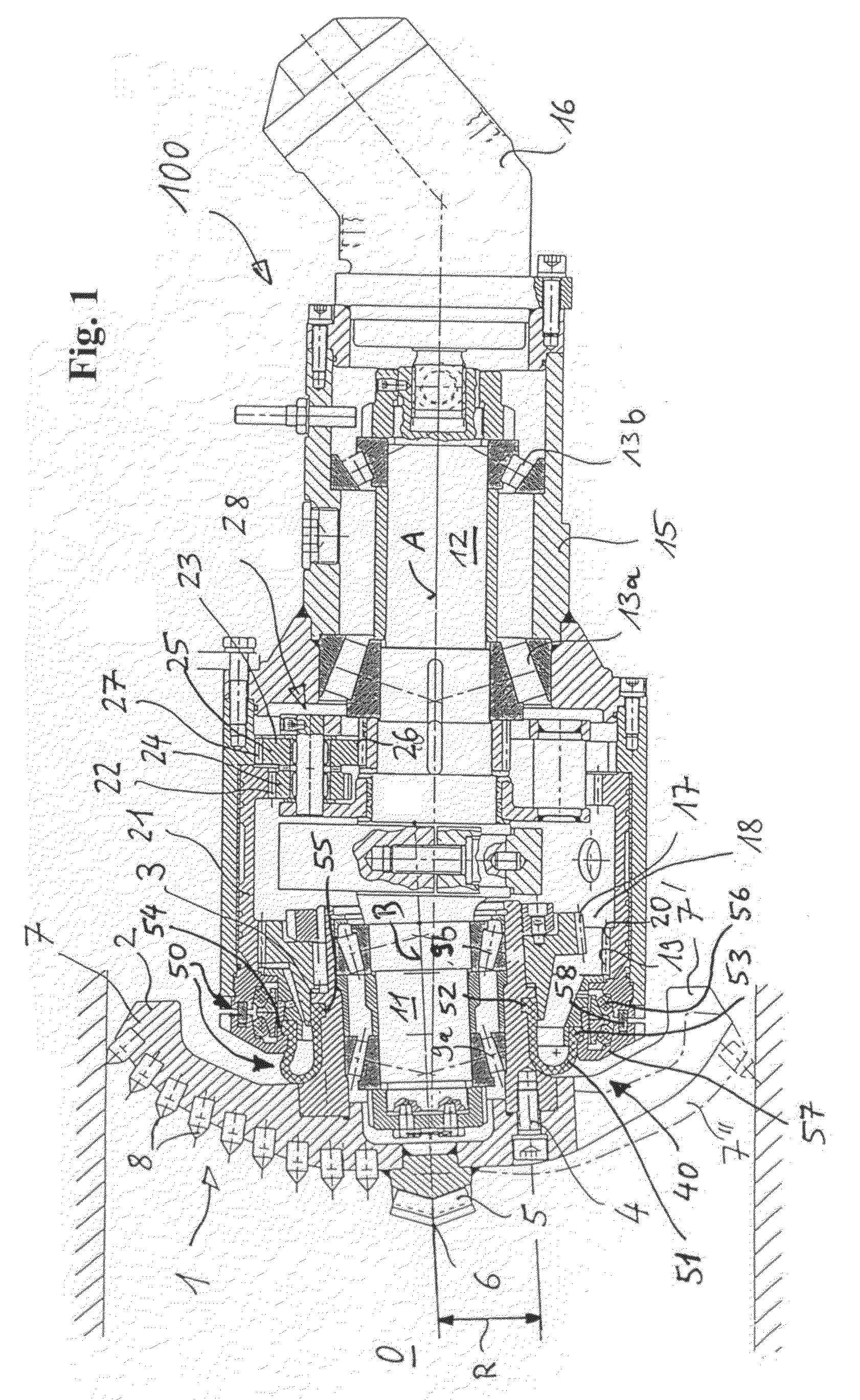
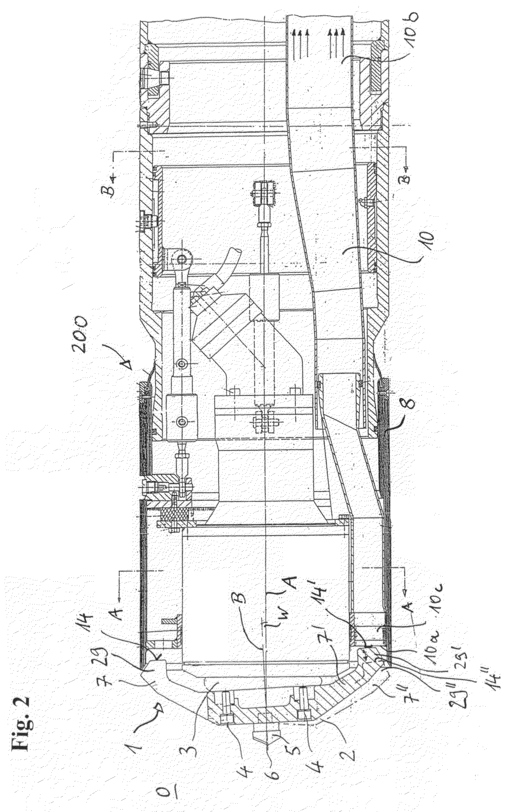
[0034]The device designated overall by 100 comprises a drill head 1 having a tool part 30, designed as a scraper disk 2, and a bearing part 3. The scraper disk 2 and the bearing part 3 are fastened to one another by a plurality of cylindrical screws 4, only one of which is shown in the drawing. The cylindrical screws 4 are arranged with uniform distribution on a pitch circle having the radius R. Splitting the drill head 1 into two parts makes it possible for the tool part 30 subjected to wear to be disassembled on the building site once the wear limit has been reached by unscrewing the screws 4, and replaced by a new or rebuilt tool part.

[0035]The scraper disk 2 is provided with a central cutter 5 whose tip 6 is situated on the axis of rotation A of the drill head. In the embodiment shown, the scraper disk 2 has three arms 7, 7′, 7″ extending radially outward, of which the arm 7 shown at the top of the drawing is equipped with a plurality of bits 8.

[0036]Via the bearing part 3, and ...


PUM


Abstract

A device for driving boreholes in the ground, having a rotationally driven main shaft with a shaft journal whose axis (B) forms an acute angle with respect to the axis (A) of the main shaft. A drill head is mounted such that it can rotate about the axis (B) of the shaft journal and has a circumferential region which runs on a complementary circumferential region, wherein the complementary circumferential region can be set rotating.

Description

BACKGROUND OF THE INVENTION[0001]The invention relates to a device for driving boreholes in the ground, as is disclosed in DE 43 32113 A 1.[0002]Horizontal boreholes, in particular having a borehole diameter of approximately 150 mm to 1 300 mm, and also vertical boreholes are produced in the ground using drilling devices in which a rotation ally driven shaft is mounted rotatably inside a machine housing. A drill head is arranged on the end of the shaft facing the rock face or the borehole bottom.[0003]The drill head can be of various designs depending on the nature of the soil in which the borehole is to be sunk. Difficulties thus frequently arise when the nature of the soil to be removed varies over the length of the drill, For instance, rock drill heads generally equipped with rollers, bits or disks become stuck in soft, for example loamy, soils; by contrast, drill heads displaying good drilling performances in loamy or loose soils rapidly fail “due to high wear on encountering ro...

Claims


Application Information

Patent Timeline
Patent Type & Authority Patents(United States)
IPC IPC(8): E21B10/00E21B4/00E21B4/16E21B10/08E21D9/087E21D9/11
CPCE21B4/006E21B4/16E21B10/083E21B10/086E21D9/113
Inventor MOHRMANN, MICHAEL
Owner AKER WIRTH
Why Eureka
Try Eureka