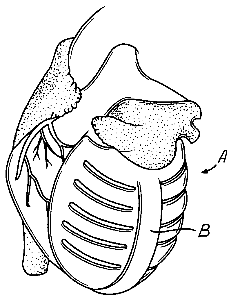
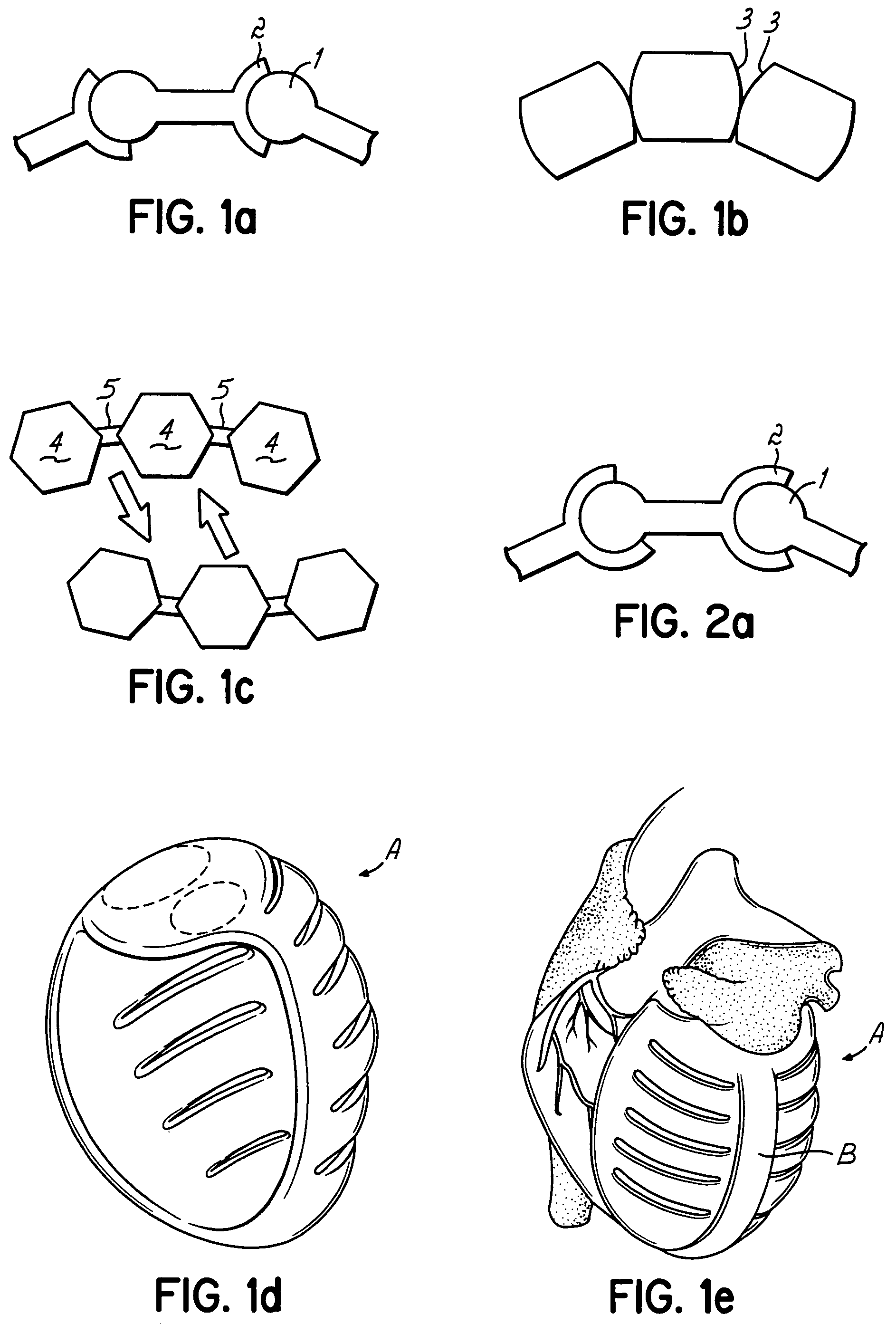
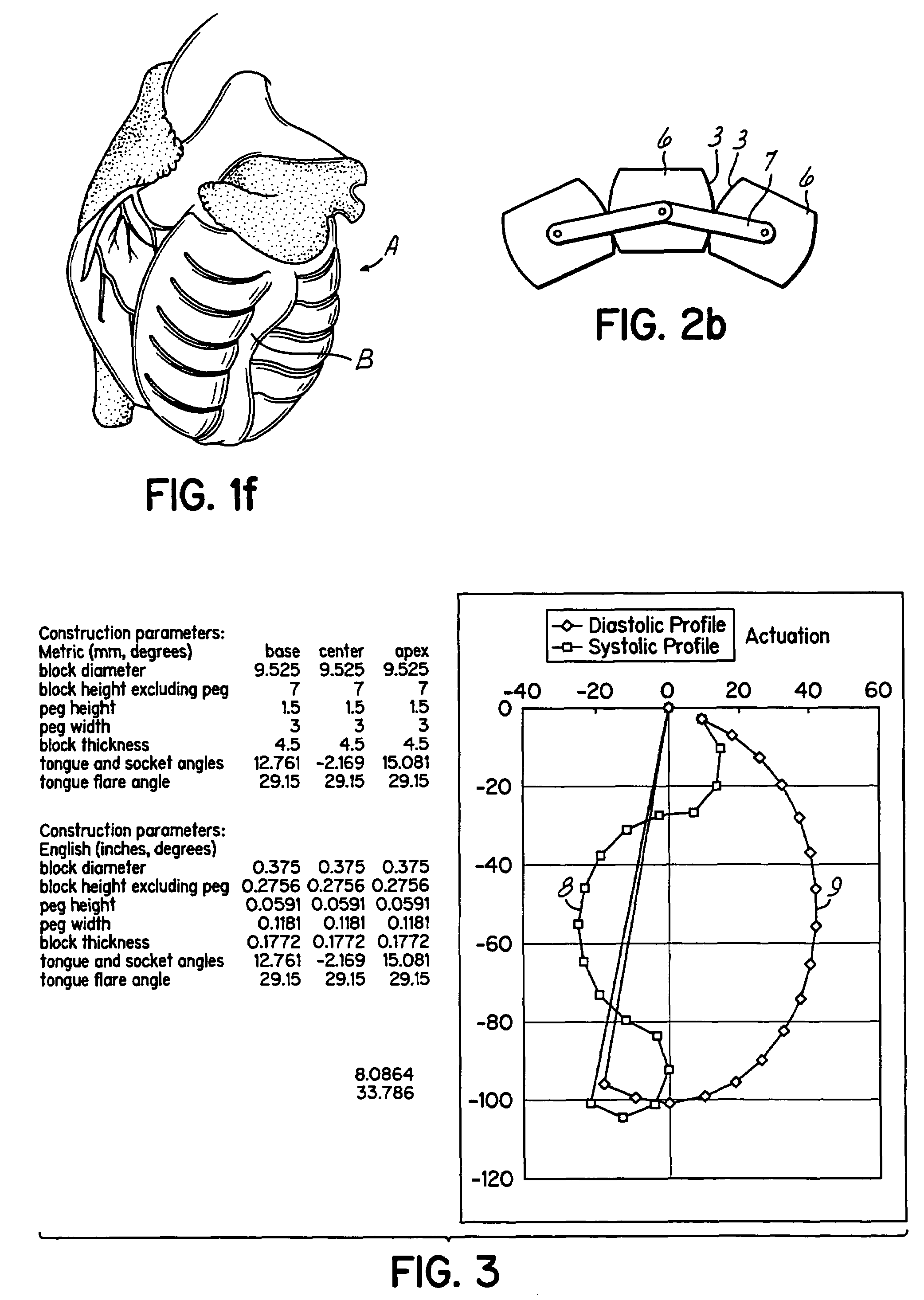
Actuation mechanisms for a heart actuation device

a heart actuation and mechanism technology, applied in the direction of heart stimulators, prostheses, therapy, etc., can solve the problems of heart muscle degeneration, heart failure, and heart failure to provide sufficient blood circulation,

Inactive Publication Date: 2010-02-09
UNIVERSITY OF CINCINNATI +1
View PDF149 Cites 806 Cited by
  • Summary
  • Abstract
  • Description
  • Claims
  • Application Information

AI Technical Summary

Problems solved by technology

More specifically, the muscle of the heart may degrade for various reasons to a point where the heart can no longer provide sufficient circulation of blood to maintain the health of a person at an acceptable level.
In fact, the heart may degrade to the point of failure and not been be able to sustain life.
Artificial heart use has been complicated by consequences of blood clots forming on the internal lining.
The most serious consequence is a breaking loose of such clots that are then propelled into various parts of the circulation.
In the event of such a clot being propelled into the brain, a disabling or fatal stroke may result.
However a more serious limitation is numbers of available donors.
All of these mechanical pumps have extensive non-living material surfaces that contact blood.
The complications of blood clotting with stroke or other serious aftermaths described with artificial hearts also occur with these mechanical auxiliary pumps.
Because of the severe shortage of human donor hearts for transplant, unsolved immunologic problems of animal donor hearts for transplants and prevalence of serious complications of artificial blood-contacting surfaces of both artificial hearts and auxiliary pumps, means of aiding the actuation of the natural heart walls have been attempted.
Muscle wraps are limited by available space relative to muscle mass required for power, as well as by intrinsic stiffness that compromises re-filling between beats.
Both muscle wraps and mechanical compression devices are limited by inability to effectively restrict volume and pressure delivery to one chamber of the heart.
Compressive patterns of either muscle wraps or mechanical devices may also distort heart valves, which can lead to valve leakage.
Several obstacles to reaching that goal have been observed in earlier and in conventional implanted medical devices, both for cardiovascular and other purpose.
First, devices in which action of mechanical members requires a residual air chamber (for example, many of the electrical ventricular assist devices) have only succeeded, clinically or experimentally, by having either an external vent or a frequently refillable compliance chamber.
Second, prolonged cyclic stress on flexing polymer membranes has often been complicated by either membrane mechanical failure or mineralization with unacceptable stiffening.
Yet such membranes, often under substantial cyclic stress are needed if moving mechanical parts are to be shielded from either affecting or being effected by tissue and tissue fluid.
Third, if mechanical members are, conversely, to contact tissue, crevasses and spaces between those moving members which do not allow and promote free flow of bathing tissue fluid are followed by several complications of such stasis.
Infection is particularly common due to restricted access to such areas by the immune system.
Interfaces between metals under such conditions are susceptible to fretting corrosions.
With or without fluid stasis, interfaces between two or more dissimilar metals may generate galvanic currents with electrolytic corrosion of one or both metals.
Further, irregular moving surfaces and edges may mechanically damage surrounding tissue or encourage immobilizing scar tissue that inhibits function.

Method used


Image

  • Actuation mechanisms for a heart actuation device
  • Actuation mechanisms for a heart actuation device
  • Actuation mechanisms for a heart actuation device

Examples


Embodiment Construction

Part List

[0044]1. ball or cylinder for a sliding rotary articulation[0045]2. socket for a sliding rotary articulation[0046]3. convex rolling surface[0047]4. rigid element for a flexing linkage[0048]5. flexible element for a flexing linkage[0049]6. links[0050]7. tension member holding rolling links in position[0051]8. profile of an articulating link actuator in full actuation[0052]9. profile of an articulating link actuator in full relaxation[0053]10. rolling surface adjacent tongue component of a tongue-in-socket articulation[0054]11. rolling surface adjacent socket component of a tongue-in-socket articulation[0055]12. tongue component[0056]13. socket component[0057]14. depth of socket[0058]15. length of tongue[0059]16. arc of the mouth of socket[0060]17. arc of base of tongue[0061]18. margin of socket[0062]19. base of tongue[0063]20. base diameter of tongue[0064]21. flare angle of tongue[0065]22. impacting projection[0066]23. impacted depression[0067]24. pin[0068]25. hook[0069]26. ...


PUM


Abstract

An actuation mechanism for assisting the operation of the natural heart has a varying shape for deforming the heart. In one embodiment, a plurality of links articulates with respect to each other for varying the shape of the actuation mechanism. The plurality of links is configured for being positioned proximate to an outer surface of the heart for deforming the heart by varying the shape of the actuation mechanism. In another embodiment, a jacket for coupling with an outer surface of the heart has a tether coupled to successive sections of the jacket. The tether is operable to be translated with respect to the jacket sections to vary the shape of the jacket for deforming the heart. In another embodiment, a plurality of concentric ring structures are coupled together to move with respect to each other in a concentric fashion. A movement mechanism coupled to the rings is operable to vary their positions with respect to each other to vary the overall shape for deforming the heart.

Description

[0001]This application is a continuation of PCT / US2004 / 018277 filed on Jun. 9, 2004, which claims priority of U.S. Provisional Patent Application No. 60 / 477,077, filed Jun. 9, 2003. The disclosure of each priority application is hereby incorporated by reference herein in its entirety.FIELD OF THE INVENTION[0002]This invention relates generally to assisting the natural heart in operation and, more specifically, to components to assist in actuating one or more walls of the natural heart.BACKGROUND OF THE INVENTION[0003]The human circulatory system is critical for survival and systematically provides nutrients and oxygen as well as removing harmful waste products from all parts of the body. The heart is a critical component of the circulatory system in that it provides pumping power. Generally the right side of the heart receives blood from the ‘systemic circulation’ (all the body except the lungs) and pumps it into the ‘pulmonary circulation’ (lungs), whereas the left side of the hear...

Claims


Application Information

Patent Timeline
Patent Type & Authority Patents(United States)
IPC IPC(8): A61M1/12A61B17/00A61B17/04A61M60/191A61M60/268A61M60/481A61M60/492
CPCA61B17/00234A61F2/2481A61M1/1068A61M1/1049A61M1/1055A61M1/122A61B17/0401A61B2017/00243A61B2017/0443A61B2017/048A61M60/148A61M60/492A61M60/481A61M60/191
Inventor MELVIN, DAVID BOYDNAY, GEOFFREY
Owner UNIVERSITY OF CINCINNATI
Why Eureka
Try Eureka