Thermally primed hydrogen-producing fuel cell system

a fuel cell and fuel cell technology, applied in the direction of cell components, electrochemical generators, sustainable manufacturing/processing, etc., can solve the problems of hydrogen-producing fuel cell systems, system cannot produce power output, and cannot accept a period of inability to meet the applied load of an energy-consuming devi

Active Publication Date: 2010-02-09
DCNS SA
View PDF63 Cites 31 Cited by
  • Summary
  • Abstract
  • Description
  • Claims
  • Application Information

AI Technical Summary

Problems solved by technology

In some applications, it may be acceptable to have a period of time in which there is a demand, or desire, to have the fuel cell system produce a power output to satisfy an applied load, but in which the system is not able to produce the power output.
In other applications, it is not acceptable to have a period where the applied load from an energy-consuming device cannot be satisfied by the fuel cell system even though there is a desire to have this load satisfied by the system.
However, hydrogen-producing fuel cell systems that require the hydrogen gas to first be produced, and perhaps purified, prior to being utilized to generate the desired power output take longer to generate this power output.
However, when the hydrogen-producing fuel processor of the fuel cell system's fuel processing assembly is not already at a desired hydrogen-producing temperature, the required time will be much longer.
In portable fuel cell systems and fuel cell systems that are designed to satisfy greater applied loads, such as loads of 10 kW or more, it may not be practical to utilize batteries to satisfy an applied load for the time required for the fuel processing assembly to be started up.

Method used


Image

  • Thermally primed hydrogen-producing fuel cell system
  • Thermally primed hydrogen-producing fuel cell system
  • Thermally primed hydrogen-producing fuel cell system

Examples


Embodiment Construction

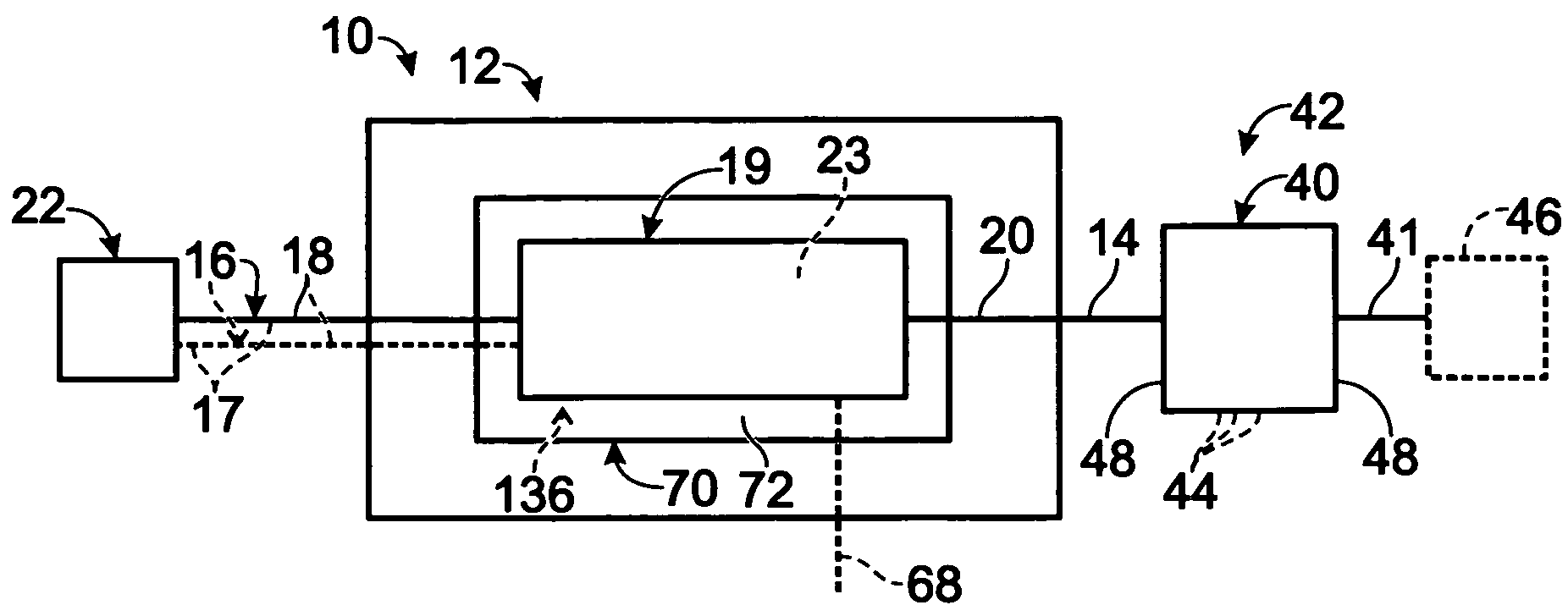
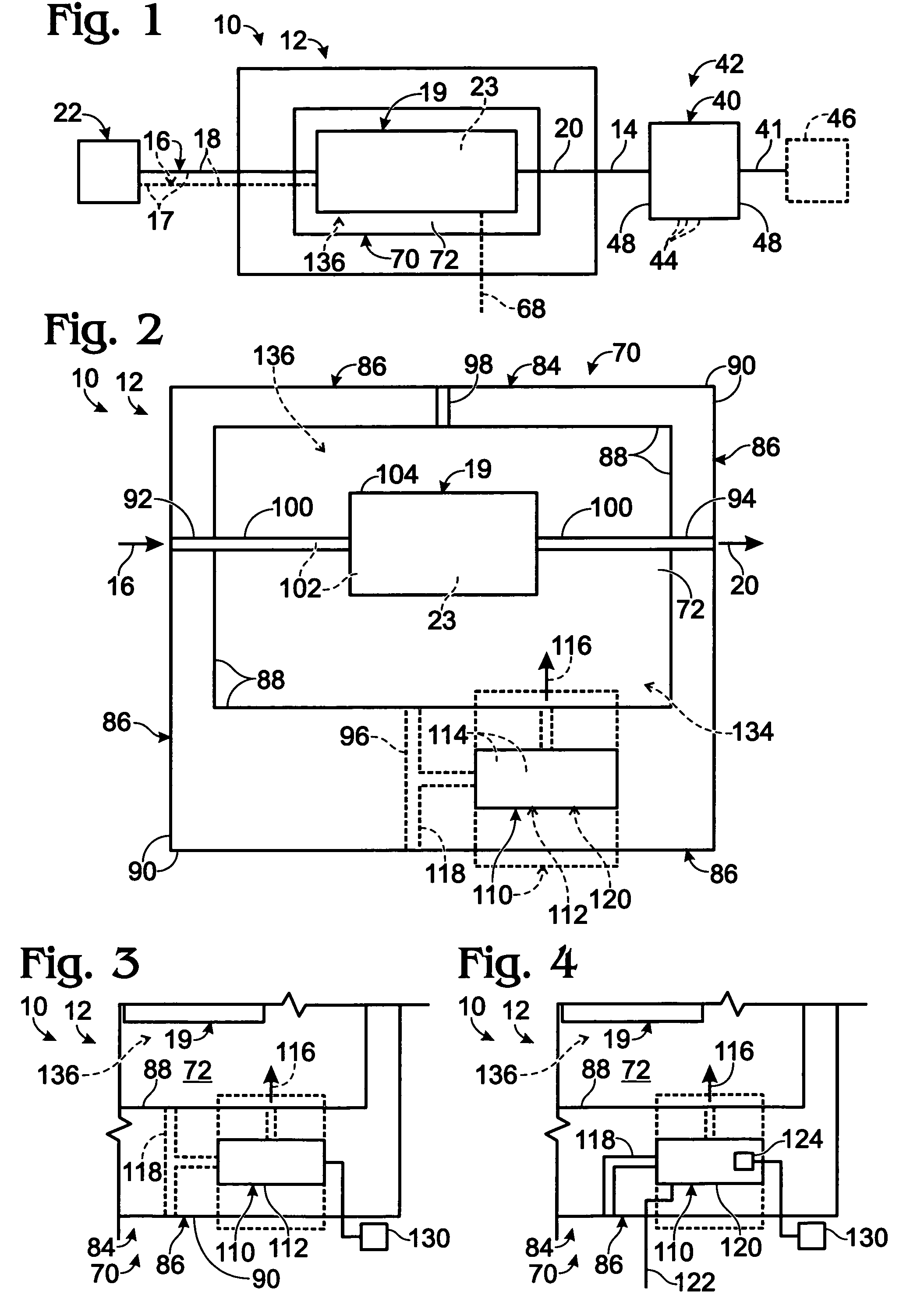
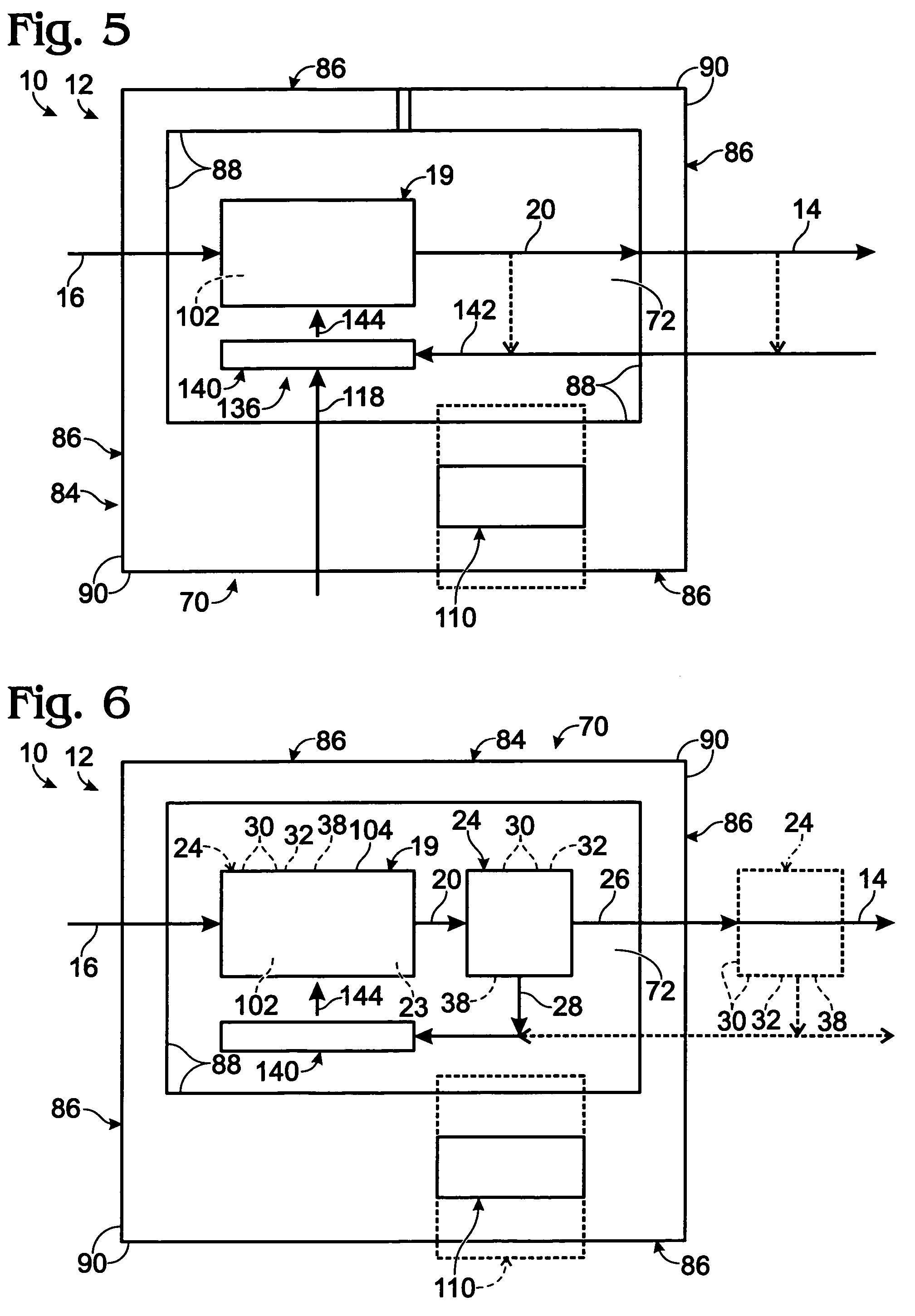
[0016]A thermally primed fuel processing assembly is shown in FIG. 1 and is indicated generally at 10. Thermally primed fuel processing assembly 10 includes a thermally primed fuel processor 12 that is adapted to produce a product hydrogen stream 14 containing hydrogen gas, and preferably at least substantially pure hydrogen gas, from one or more feed streams 16. Feed stream 16 includes at least one carbon-containing feedstock 18, and may include water 17. Fuel processor 12 is any suitable device, or combination of devices, that is adapted to produce hydrogen gas from feed stream(s) 16. Accordingly, fuel processor 12 includes a hydrogen-producing region 19, in which a hydrogen gas is produced using any suitable hydrogen-producing mechanism(s) and / or process(es). The product hydrogen stream may be delivered to a fuel cell stack 40, which is adapted to produce an electric current, or power output, 41 from hydrogen gas and an oxidant, such as air. An air stream is illustrated at 43 in ...


PUM

PropertyMeasurementUnit
threshold temperatureaaaaaaaaaa

Abstract

Thermally primed fuel processing assemblies and hydrogen-producing fuel cell systems that include the same. The thermally primed fuel processing assemblies include at least one hydrogen-producing region housed within an internal compartment of a heated containment structure. In some embodiments, the heated containment structure is an oven. In some embodiments, the compartment also contains a purification region and / or heating assembly. In some embodiments, the containment structure is adapted to heat and maintain the internal compartment at or above a threshold temperature, which may correspond to a suitable hydrogen-producing temperature. In some embodiments, the containment structure is adapted to maintain this temperature during periods in which the fuel cell system is not producing power and / or not producing power to satisfy an applied load to the system. In some embodiments, the fuel cell system is adapted to provide backup power to a power source, which may be adapted to power the containment structure.

Description

FIELD OF THE DISCLOSURE[0001]The present disclosure is directed generally to hydrogen-producing fuel cell systems, and more particularly, to hydrogen-producing fuel processing systems with thermally primed hydrogen-producing regions.BACKGROUND OF THE DISCLOSURE[0002]As used herein, a fuel processing assembly is a device or combination of devices that produces hydrogen gas from one or more feed streams that include one or more feedstocks. Examples of fuel processing assemblies include steam and autothermal reformers, in which the feed stream contains water and a carbon-containing feedstock, such as an alcohol or a hydrocarbon. Fuel processors typically operate at elevated temperatures. In endothermic fuel processing reactions, such as in steam reforming fuel processing assemblies, the heat required to heat at least the hydrogen-producing region of the fuel processing assembly to, and maintain the region at, a suitable hydrogen-producing temperature needs to be provided by a heating a...

Claims


Application Information

Patent Timeline
Patent Type & Authority Patents(United States)
IPC IPC(8): H01M8/00H01M8/04
CPCH01M8/04022H01M8/04037H01M8/04268H01M8/04619H01M8/04626H01M8/04738H01M8/0618H01M8/0631C01B3/38C01B3/48C01B2203/0475Y02P20/128C01B2203/0495C01B2203/066C01B2203/0811C01B2203/0822C01B2203/0827C01B2203/1223C01B2203/1229C01B2203/1241C01B2203/1247C01B2203/1288H01M8/0662H01M8/0668H01M8/0687H01M16/003H01M2250/10Y02B90/14C01B2203/0233C01B2203/0244C01B2203/0283C01B2203/0405C01B2203/043C01B2203/047C01B2203/0485Y02B90/10Y02P20/10Y02E60/50H01M8/04H01M8/06Y02E60/32
Inventor EDLUND, DAVID J.
Owner DCNS SA
Why Eureka
Try Eureka