Eureka AIR delivers breakthrough ideas for toughest innovation challenges, trusted by R&D personnel around the world.

Structural joint strain monitoring apparatus and system

Active Publication Date: 2010-02-09
SCHLUMBERGER TECH CORP
View PDF15 Cites 14 Cited by
  • Summary
  • Abstract
  • Description
  • Claims
  • Application Information

AI Technical Summary

Benefits of technology

[0017]The jacket means may have a lower mechanical strength than the structural joint such that the jacket means does not interfere with any movement of the joint, and any such movement is translated into strain within a jacket element and/or the or each web element.
[0018]The jacket means may alternatively have an equal or higher mechanical strength than the structural joint, such that the jacket mean

Problems solved by technology

The flow of oil or gas within such pipes can cause vibrations within the pipes and relative movement between pipes at joints.
These vibrations and movement can ultimately lead to damage or failure of the joint.
Both ROVs and pigs can only provide intermittent measurements, and inspection using these methods is costly.

Method used


Image

  • Structural joint strain monitoring apparatus and system
  • Structural joint strain monitoring apparatus and system
  • Structural joint strain monitoring apparatus and system

Examples


second embodiment

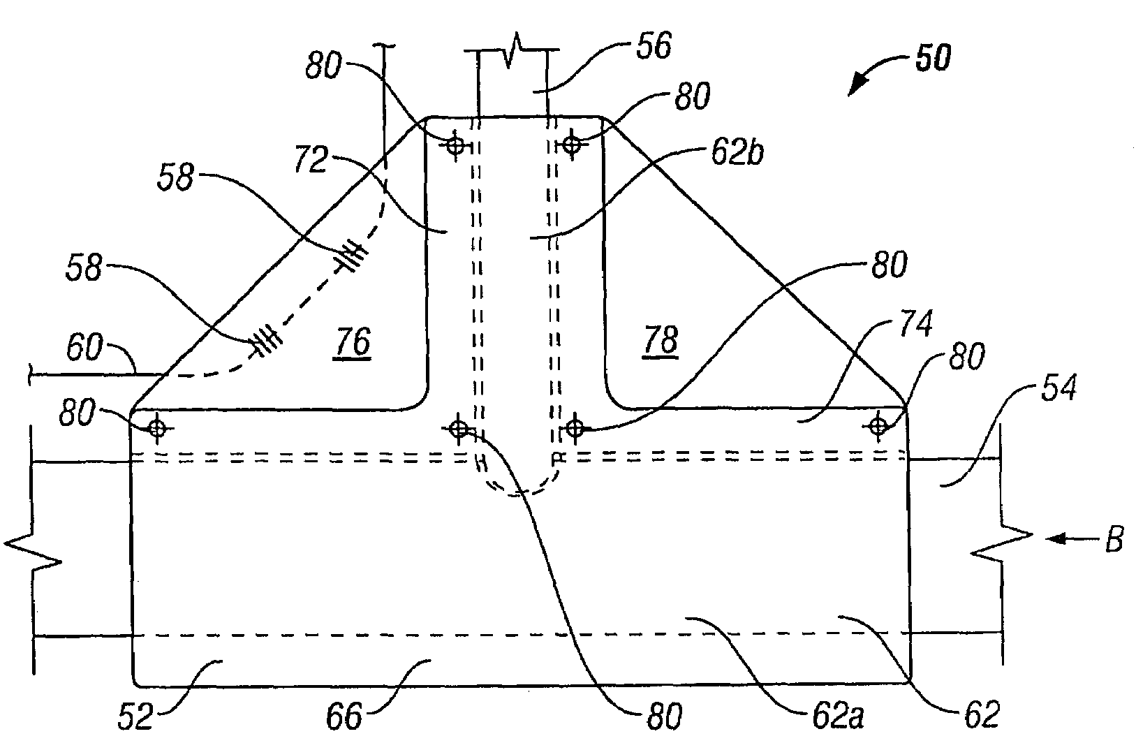
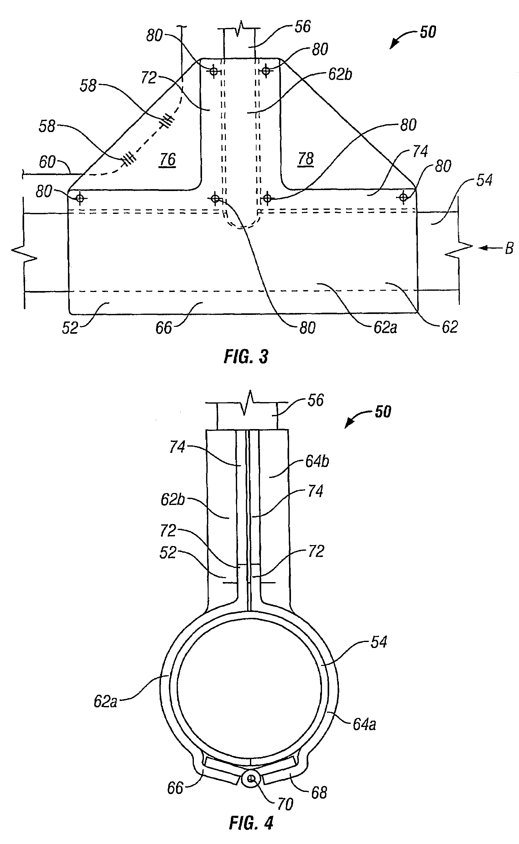
[0044]FIGS. 3 and 4 show structural joint strain monitoring apparatus 50 according to the invention.

[0045]The apparatus 50 comprises jacket means 52, for location around a T-joint between two generally perpendicular pipes 54, 56, and two FBG strain sensors 58 provided within an optical fibre 60.

[0046]The jacket means 52 comprises two jacket elements 62, 64 which together define a generally T-shaped compartment of complimentary size and shape to the T-joint between the two pipes 54, 56, such that the T-joint may be closely received within the jacket means 52.

[0047]The jacket means 52 is fabricated in a glass fibre / polyester resin composite material and is designed to be sufficiently mechanically weak as to not interfere with any movement of the joint pipes 54, 56.

[0048]Each jacket element 62, 64 is generally T-shaped, having a primary hemi-cylindrical part 62a, 64a, for receiving the first pipe 54, and a secondary hemi-cylindrical part 62b, 64b extending generally perpendicularly out...


PUM


Abstract

Structural joint strain monitoring apparatus 92 comprises jacket means 52 in the form of first and second jacket elements 62, each having a primary jacket part 62a and substantially perpendicular secondary jacket part 62b which together define a compartment for receiving a joint, between two pipes 54, 56, to be monitored. The jacket means 52 additionally comprises two primary web elements 76, 78 provided between the primary and secondary jacket parts 62a, 62b. Three fiber Bragg grating (FBG) strain sensors 96, 98, 100 and an FBG temperature sensor 102 are provided within an optical fiber 104, bonded to the primary web elements 76, 78 and each end of the second jacket element 62 respectively, for measuring strain or temperature at their respective locations. The FBG sensors 96, 98, 100, 102 are optically coupled, via optical fiber 104, to optical fiber sensor interrogation apparatus 94, operable to interrogate each FBG sensor.

Description

FIELD OF THE INVENTION[0001]The invention relates to structural joint strain monitoring apparatus and to a structural joint strain monitoring system incorporating the apparatus.BACKGROUND OF THE INVENTION[0002]Oil and gas extraction pipelines generally include joints between sections of pipe and between the main pipe and bypass pipes. The flow of oil or gas within such pipes can cause vibrations within the pipes and relative movement between pipes at joints. These vibrations and movement can ultimately lead to damage or failure of the joint. It is desirable to be able to monitor the physical conditions (such as strain) experienced at pipe joints. These measurements should ideally be available in real time in order that conditions causing high loads and potential failure can be identified. Current practice within the oil and gas industries, includes monitoring pipe joints by visual inspection using remotely operated vehicles (ROVs) or using intelligent pigs travelling within the pipe...

Claims


Application Information

Patent Timeline
IPC IPC(8): G02B6/44
CPCF16L41/021F17D5/02G01B11/165G01B11/18G01L1/246
Inventor ROBERTS, RICHARD DAMON GOODMAN
Owner SCHLUMBERGER TECH CORP
Why Eureka
Eureka Blog
Learn More