Eureka AIR delivers breakthrough ideas for toughest innovation challenges, trusted by R&D personnel around the world.

Method of producing ceramic substrates

Inactive Publication Date: 2012-10-25
NGK INSULATORS LTD
View PDF0 Cites 1 Cited by
  • Summary
  • Abstract
  • Description
  • Claims
  • Application Information

AI Technical Summary

Benefits of technology

[0017]According to the present invention, in breaking the base plate along the dividing grooves, it is possible to prevent the fracture of the base plate along a line different from the dividing grooves.

Problems solved by technology

According to the prior arts, in breaking a base plate along dividing grooves, the base plate may be broken along a line different from the dividing grooves to result in a reduction of yield.
In this case, however, the mechanical strength of the base plate would be considerably lowered so that the base plate may be easily broken during handling for printing etc.
It is thus impossible to make the dividing groove deeper than a predetermined depth.

Method used


Image

  • Method of producing ceramic substrates
  • Method of producing ceramic substrates
  • Method of producing ceramic substrates

Examples


example 1

[0047]A base plate 1 made of a translucent alumina ceramics was produced as follows. That is, 100 weight parts of alumina powder and 0.025 weight parts of magnesia as powdery raw materials, 30 weight parts of a polybasic acid ester as a dispersant, 4 weight parts of MDI resin as a gelling agent, 2 weight parts of “MALIALIM AKM0351” (trade name, supplied by NOF corporation) as a dispersant, and 0.2 weight parts of triethylamine as a catalyst were mixed to obtain slurry. The slurry was then casted at room temperature into a mold made of an aluminum alloy which has protrusions each having an inverted shape of a dividing groove, maintained at room temperature for 1 hour, and removed from the mold after the solidification. Further, the molded body was maintained at room temperature for 2 hours and then at 90° C. for 2 hours to obtain a dried molded body of powder having a shape of a base plate. It was then calcined at 1200° C. in air to obtain a calcined body. The calcined body was then ...

examples 2 and 3

[0061]Test was performed according to the same procedure as the Example 1 except that the width of the opening and angle of the bottom of the groove were changed as shown in Table 1, and the results were shown in Table 1.

TABLE 1ComparativeComparativeExample 1Example 2Example 3Example 1Example 2Width of opening 0.3 mm 0.1 mm 0.5 mm 0.3 mm 0.3 mmat surface: mmAngle at bottom of60°25°90°60°60°groove: °Depth of groove: mm0.26 mm0.26 mm0.26 mm0.26 mm0.26 mmShape of spacingTangentialTangentialTangentialCircleCurvedArcArcArcArcForce required0.6 ± 0.10.6 ± 0.10.6 ± 0.10.6 ± 0.30.7 ± 0.3for breaking: N / mm2Shift from0 / 100 / 100 / 103 / 108 / 10dividing groove


PUM

PropertyMeasurementUnit
Angleaaaaaaaaaa
Widthaaaaaaaaaa
Digital informationaaaaaaaaaa

Abstract

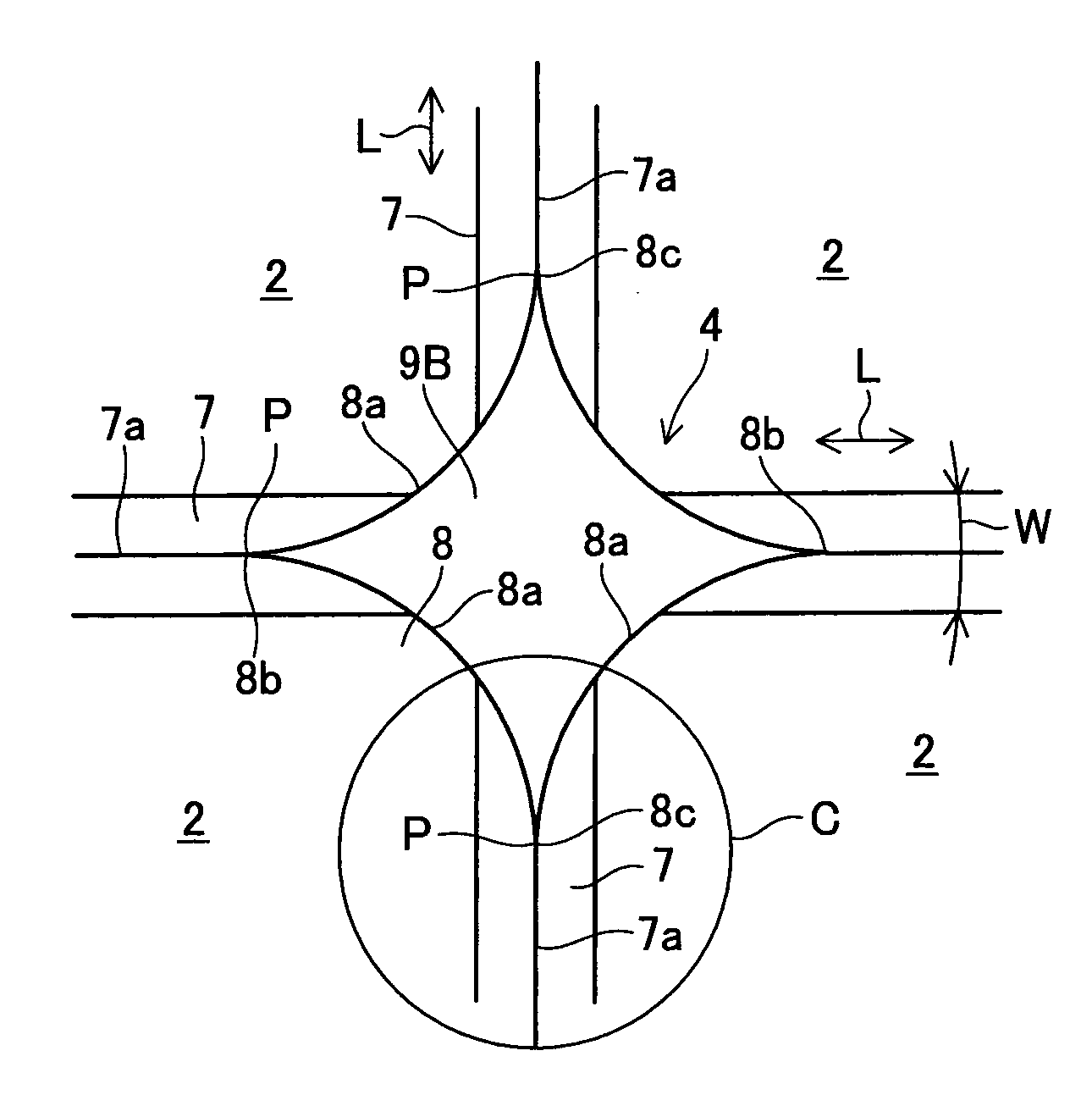
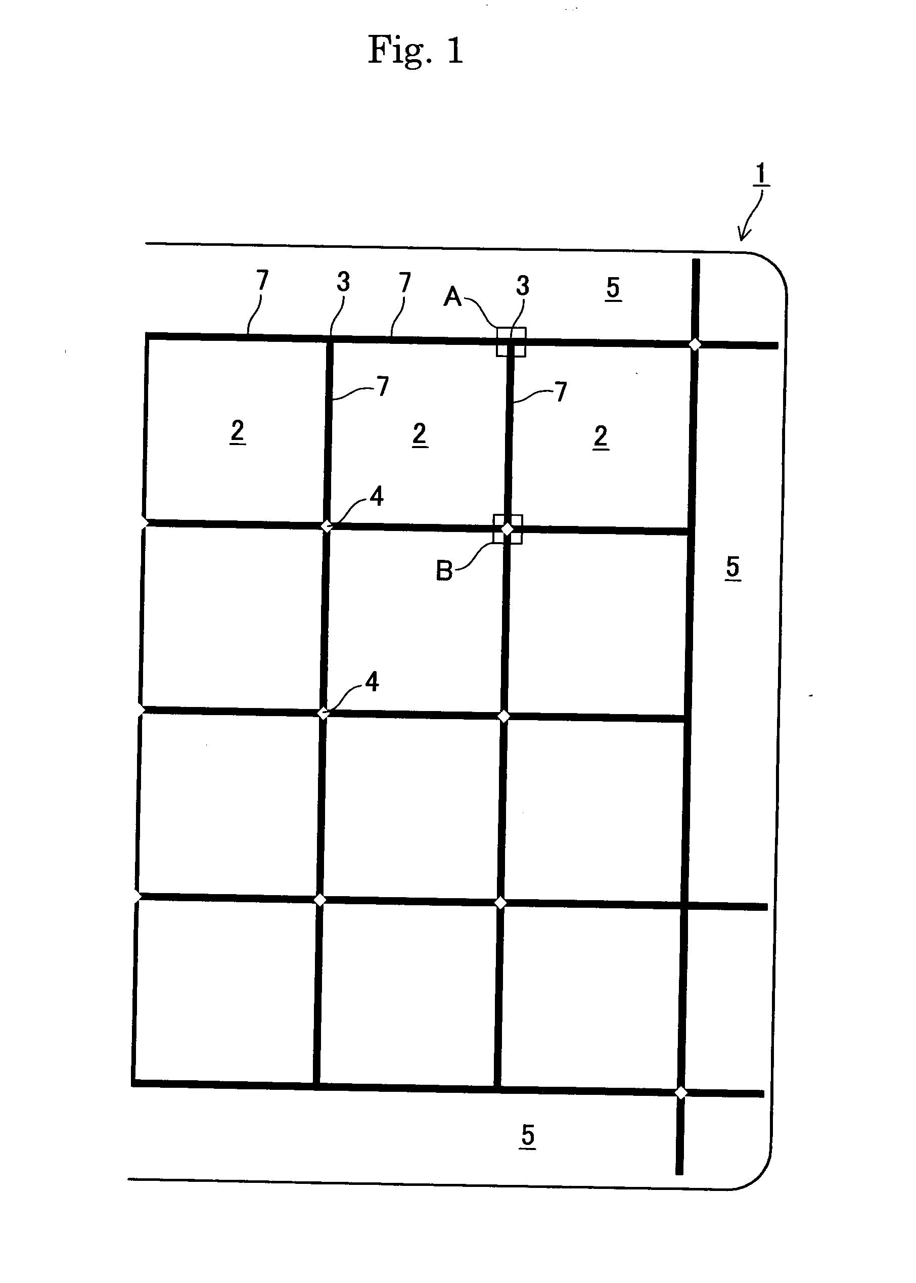
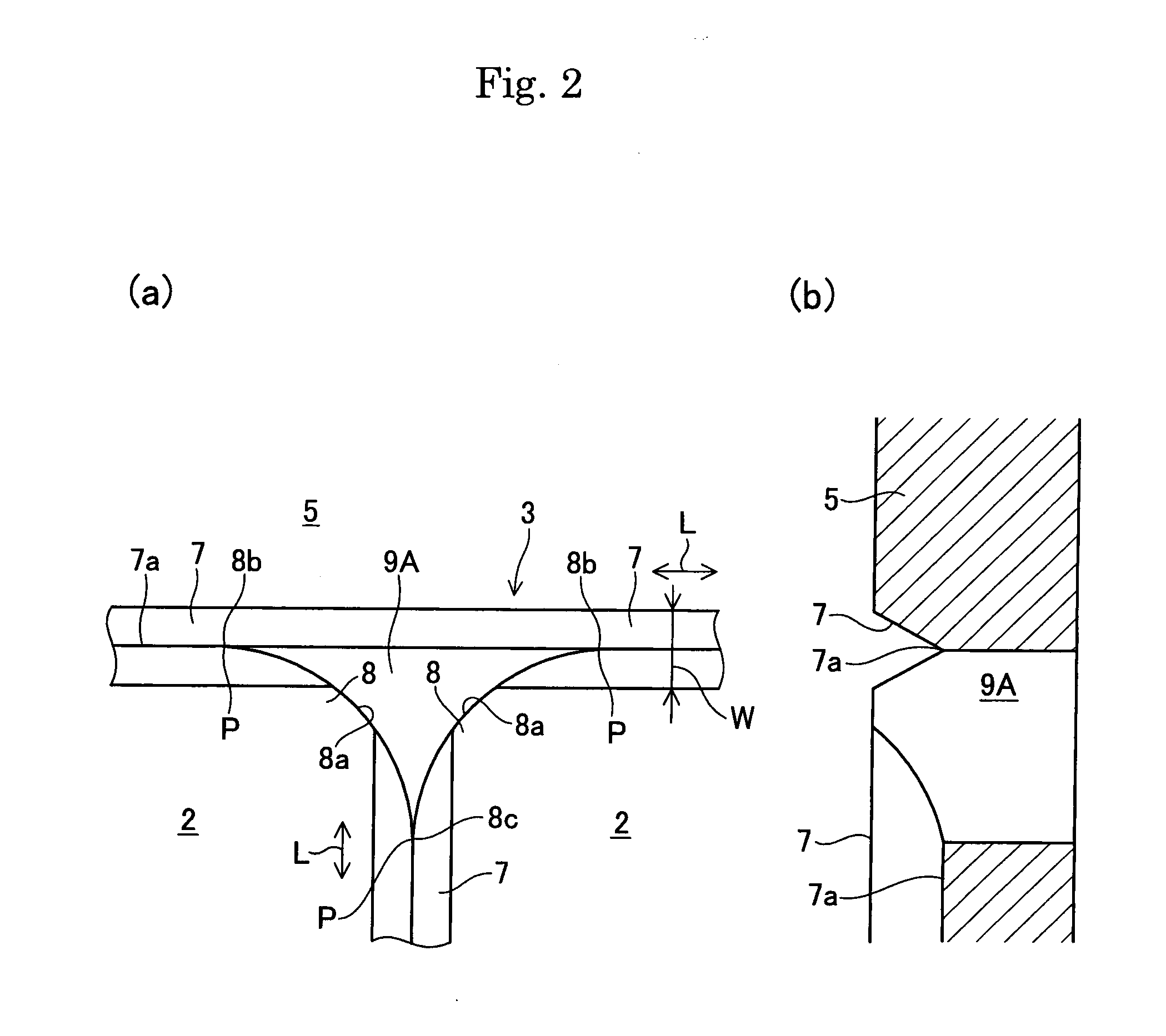
A ceramic base plate is divided into a plurality of substrate regions 2 each having corner part 8. A dividing groove 7 is formed between the substrate regions 2 adjacent with each other. The corner part 8 of each of the substrate regions 2 faces a spacing 9B communicated with the dividing groove 7. At least a part of the corner part 8 is arc-shaped. The arc-shaped part of the corner part is tangent to a center line 7a of the dividing groove 7 at a cross point “P” of the spacing 9B with the dividing groove 7. The ceramic base plate is broken along the dividing groove 7 to produce ceramic substrates.

Description

[0001]This application claims the benefit of Japanese Patent Application No. P2011-092651, filed on Apr. 19, 2011, the entirety of which is incorporated by reference.BACKGROUND OF THE INVENTION[0002]1. Field of the Invention[0003]The present invention relates to a method of producing ceramic substrates by breaking a ceramic base plate.[0004]2. Background Arts[0005]Alumina ceramics has been widely used for a substrate for electronic devices owing to its characteristics such as electrical insulation and chemical stability. In producing such substrates, many substrate regions are provided in a single base plate of a large area, for facilitating its handling and for improving subsequent production efficiency of electronic devices such as printing of wiring patterns and mounting of semiconductor devices. In producing such substrates, breaking grooves (dividing grooves) are formed on a surface of the base plate for facilitating the breaking into respective pieces. Such dividing grooves ma...

Claims


Application Information

Patent Timeline
IPC IPC(8): B26F3/00
CPCB28D5/0011H05K2201/09145H05K2201/0909H05K3/0052Y10T225/12
Inventor MIYAZAWA, SUGIOWATANABE, KEIICHIROOHASHI, TSUNEAKI
Owner NGK INSULATORS LTD
Why Eureka
Eureka Blog
Learn More