Integrated electric gas turbine
- Summary
- Abstract
- Description
- Claims
- Application Information
AI Technical Summary
Benefits of technology
Problems solved by technology
Method used
Image

Examples
Embodiment Construction
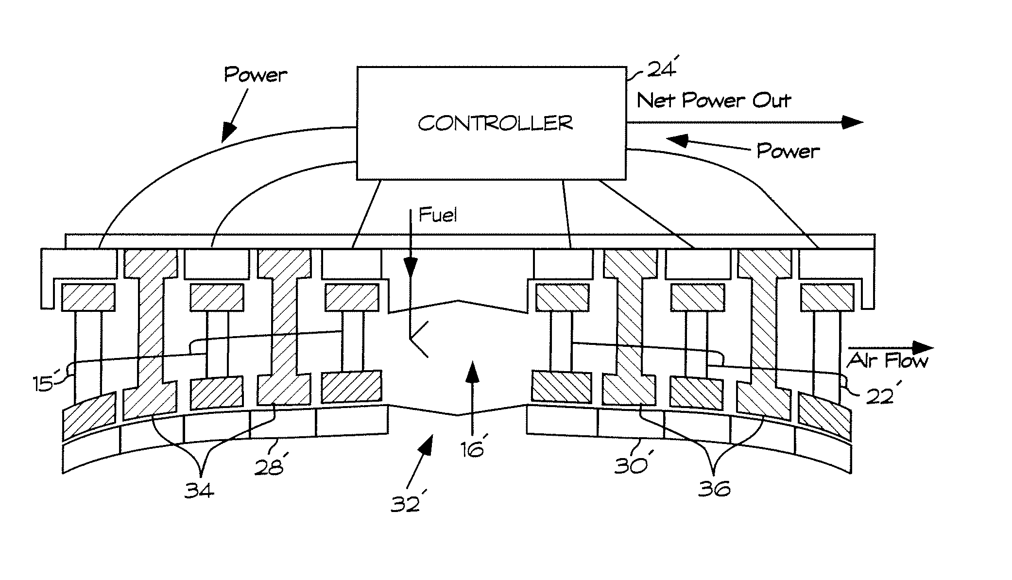
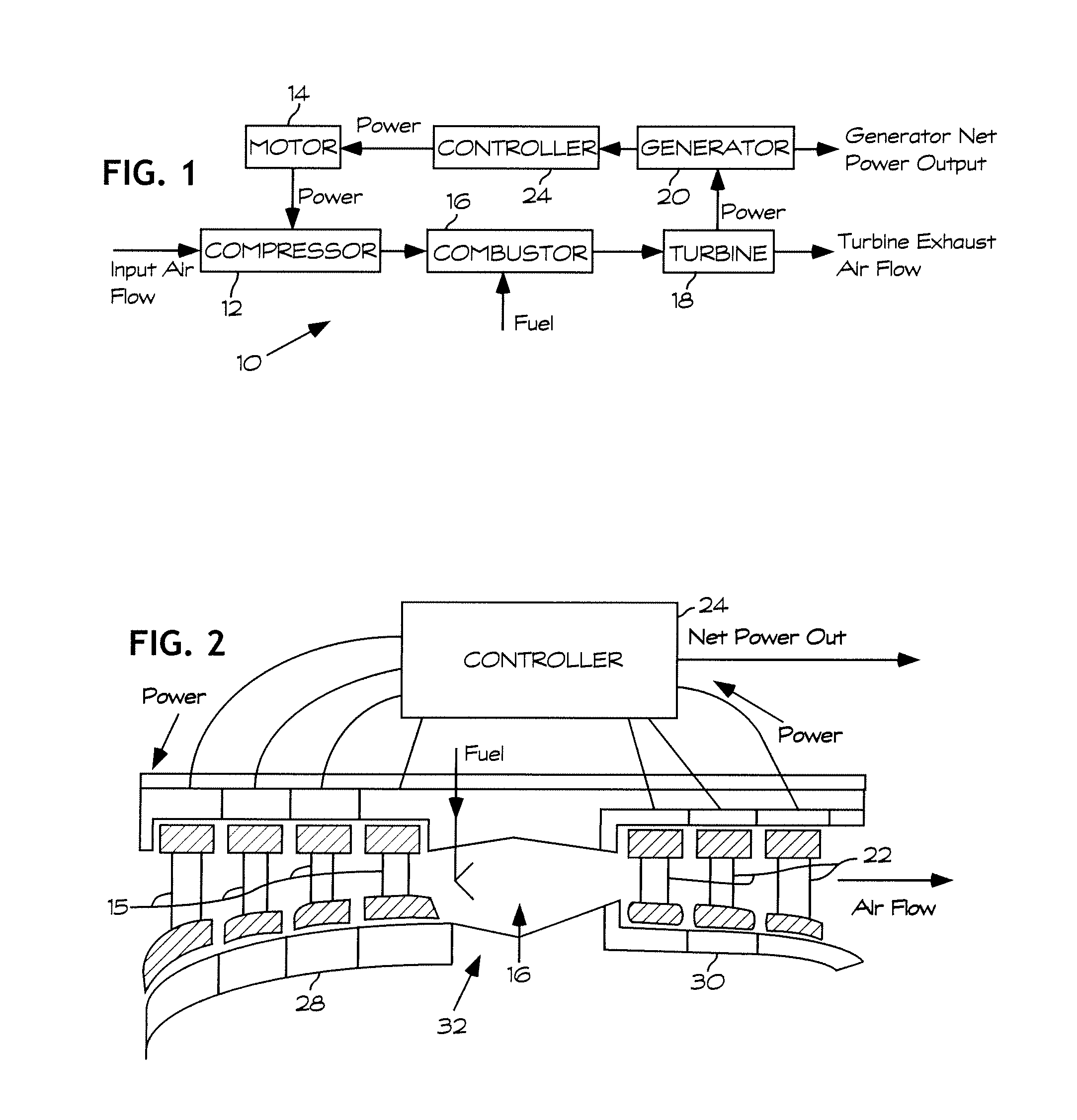
[0025]FIG. 1 is a block diagram that illustrates the basic structural features of an integrated electric gas turbine 10 according to the present invention. As shown in FIG. 1, air enters a compressor 12, which may comprise a series of rotating rings of cascaded airfoils 15, shown in FIG. 2, driven by an integrated electric motor structure 14. Either conventional or levitating magnetic bearings (not shown) can be used to support the rotating airfoil rings 15, which act as both compressor rows and electric motor armatures. For each row, power is transferred to the inside, outside or both surfaces of the ring via electromagnetic induction just as in a conventional electric motor rotor. The airfoil rings 15 act to compress the gas just as in a conventional compressor. The rings 15 can be of axial, mixed or radial flow design. Any type of particular electric motor design can be used, including conventional or superconducting, A.C. or D.C., synchronous or induction, 2-pole, 4-pole with br...
PUM
 Abstract
Description
Claims
Application Information
 - Generate Ideas
- Intellectual Property
- Life Sciences
- Materials
- Tech Scout
- Unparalleled Data Quality
- Higher Quality Content
- 60% Fewer Hallucinations
Browse by: Latest US Patents, China's latest patents, Technical Efficacy Thesaurus, Application Domain, Technology Topic, Popular Technical Reports.
© 2025 PatSnap. All rights reserved.Legal|Privacy policy|Modern Slavery Act Transparency Statement|Sitemap|About US| Contact US: help@patsnap.com