Clip-on light apparatus

a technology of light apparatus and clip, which is applied in the direction of lighting support devices, lighting and heating apparatus, instruments, etc., can solve the problems of not being very well adapted to use with reading glasses, lighting devices generating a significant amount of heat, and being subject to being frequently taken off and put back, etc., to achieve greater freedom of light positioning, increased holding force, and more versatile

Inactive Publication Date: 2010-02-16
WATERS
View PDF10 Cites 61 Cited by
  • Summary
  • Abstract
  • Description
  • Claims
  • Application Information

AI Technical Summary

Benefits of technology

[0010]In accordance with one form of the invention, lighted glasses, and preferably those adapted for reading which include corrective lenses, e.g. magnifiers, are provided to enable conventional sized text to be clearly read in dimly lit areas when held at a normal range of reading distances at which a user typically reads such material, such as between ten inches and eighteen inches from the lenses. High strength lights and light mounts therefor cooperate to light the reading area with a maximum amount of light provided in the reading distance range. More particularly, highly efficient and high intensity light emitting diodes (LEDs) are mounted in housings configured to fix narrow beams of light to be directed slightly inward toward each other so that the beams overlap in the reading distance range thus providing double the amount of light for reading over that provided by a single one of the lights. To this end, the housings are attached adjacent outer portions of the lenses so that the inwardly directed light beams light up the areas generally in front of the glasses, i.e. in its field of view, and which begins spaced forwardly therefrom, i.e. generally coinciding with the start of the reading distance range. Further, the small size and efficient nature of the preferred solid-state material, i.e. InGaN (indium gallium nitride), for the LEDs, allows very small power supplies to be used such as disc-shaped coin cell batteries for powering the LEDs which, in turn, allows both the light source and power source herein to be self-contained in a highly compact housing therefor. In this regard, the present invention also contemplates the provision of compactly sized lighting modules as described above that can be attached to reading or other glasses either removably or fixed in a more permanent fashion as described hereinafter, or to other items typically worn as headgear such as hats or the like.
[0011]The beams of light from the LEDs generate conical-shaped lighted areas such that upon intersection they cooperate to form a conical overlapping lighted area in which the brightness of the light is effectively doubled over that provided by a single LED. The conical overlapping lighted area increases in size as distances increase from the lenses. As is known, light tends to dissipate the further it is from its source. The overlapping conical lighted area is such that the peripheral areas in the field of view of the lenses that do not receive the double light strength of the overlapping light beams are closest to the lenses where light dissipation has its least effect in the reading distance range, whereas the overlapping lighted area increases in size further from the lenses with a corresponding decrease in the single light strength peripheral areas on either side of the cone of overlapping light. Thus, as light dissipates and distances increase from the lenses, the lighting provided will not suffer as the double light strength of the overlapping conical region of light will more than make up for the effects of light dissipation in the reading distance range.
[0014]The preferred LEDs herein are a small lightweight device that provides a very bright light, while consuming very little power. As such, the batteries enclosed in the housing are small and do not need to be changed as frequently as devices that utilize incandescent lights or fiber optics, which require large batteries. The LEDs provide a relatively narrow beam of light that can be well focused in a particular direction. For example, if two light modules are mounted on a pair of glasses, the LEDs in each module are positioned such that the cones of light produced by the LEDs in the light modules begin intersecting at a point closely adjacent to or coinciding with the start of the range of ideal reading distances. As such, the illuminated reading portion receives the brightest light possible since the intersection of both cones of light are trained on that area. Another advantage of using the high intensity LEDs is that because they consume such a small amount of power, virtually no heat is dissipated. Therefore, a user is able to wear eyeglasses having the light modules mounted thereon, for longer periods of time without suffering from heat and without being bothered by the weight of the devices.
[0017]In another embodiment, a compact clip-on light apparatus is provided including a light module, a clipping mechanism, and a polyaxial coupling joint between the light module and the clipping mechanism. The polyaxial coupling joint permits the light module to be pivoted about a plurality of axes for directing light in a desired direction. The polyaxial coupling joint provides advantages over prior art lighted glasses or prior clip-on light devices that only permit pivoting of the light source along a single pivot axes. The polyaxial coupling joint, on the other hand, permits light from the light module to be directed in a plurality of directions without necessitating that the item to which the light module is attached be adjusted or shifted. Preferably, the polyaxial coupling joint is configured so that the light module is pivotally rotatable about one pivot axis to provide even greater freedom of light positioning. The clip-on light apparatus with the polyaxial coupling joint, therefore, is more versatile than prior clip-on lighting devices, especially when coupled to eyeglasses or headgear, because the direction of the light can be changed by pivoting or rotating the light in one of a variety of directions relative to the frame instead of the user needing to turn their head or reposition the device.
[0018]In a preferred form, the clip-on light apparatus includes a retention device that is arranged and configured to restrict movement of the light module about a pivot axis at the polyaxial coupling joint. Most preferably, the pivot axis for which the retention device is operable is a variable pivot axis that itself is pivotal in a plane with the module pivoted laterally to either side of the plane. The retention device is operable to generate a holding force at the coupling joint so that the amount of pivoting of the light module about the pivot plane can be controlled. Depending on whether the retention device is loosened or tightened, more or less pivoting of the light module about the pivot plane can occur. The resistance to pivoting about the pivot plane via the retention device can generate minimal play within the polyaxial coupling joint about the pivot plane. For example, tightening the retention device provides increased holding forces on the polyaxial coupling joint resulting in more resistance to pivoting of the light module laterally about the pivot plane. Conversely, loosening the retention device permits greater freedom of movement in the polyaxial coupling joint due to lower holding forces directed on the polyaxial coupling joint.

Problems solved by technology

Generally, however, they have not been very well adapted for use with reading glasses.
As is known, these types of glasses typically are not worn all the time, and are subject to being frequently taken off and put back on.
Unfortunately, such lighting devices generate a significant amount of heat.
Smaller, less powerful incandescent lights still may make the wearer feel quite uncomfortable after even a short while due to the proximity of the light source and the wearer's face.
Further decreasing the size of the incandescent lights, to the point where the wearer is comfortable, may cause light output to be very dim and therefore unusable for illuminating reading material that are held at distances optimal for reading.
However, a lower intensity light bulb, which may be preferable to reduce heat or increase battery life, may result in less than optimal lighting at the optimal reading distance, causing eye-strain and discomfort.
Unfortunately, such devices suffer from a rather major limitation.
As such, head gear such as worn by surgeons having a fiber optic lighting device must at all times stay tethered to a fiber optic light source, which severely restricts the mobility of the user and thus the ease of use of the headgear.
A portable light source that stays connected to the fiber optic light head via electrical cables is less than desirable in terms of the need to be able to conveniently carry the light source, and the inconveniences associated with dangling connecting lines.
An additional problem that exists with fiber optic devices, as well as incandescent lighting devices, is rapid battery consumption.
Incandescent light bulbs are known to consume large amounts of power.
Similarly, a fiber optic device, since it requires a strong lighting source, also requires a large amount of power.
As a result, the user is forced to change batteries often or stay tethered to a constant power source or light source.
Another disadvantage in prior art lighting devices is the manner in which surfaces are illuminated.
However, such a single narrow beam would not be particularly helpful in reading textual material as the beam would have to be continually shifted across the page being read.
On the other hand, lights used with glasses generally tend to be very inefficient in their use of the light they generate as large amounts of light are cast beyond the field of view of the glasses.
Adjustable lights are less than desirable as they require a user to make sure the lights are properly positioned each time the glasses are used.

Method used


Image

  • Clip-on light apparatus
  • Clip-on light apparatus
  • Clip-on light apparatus

Examples


Embodiment Construction

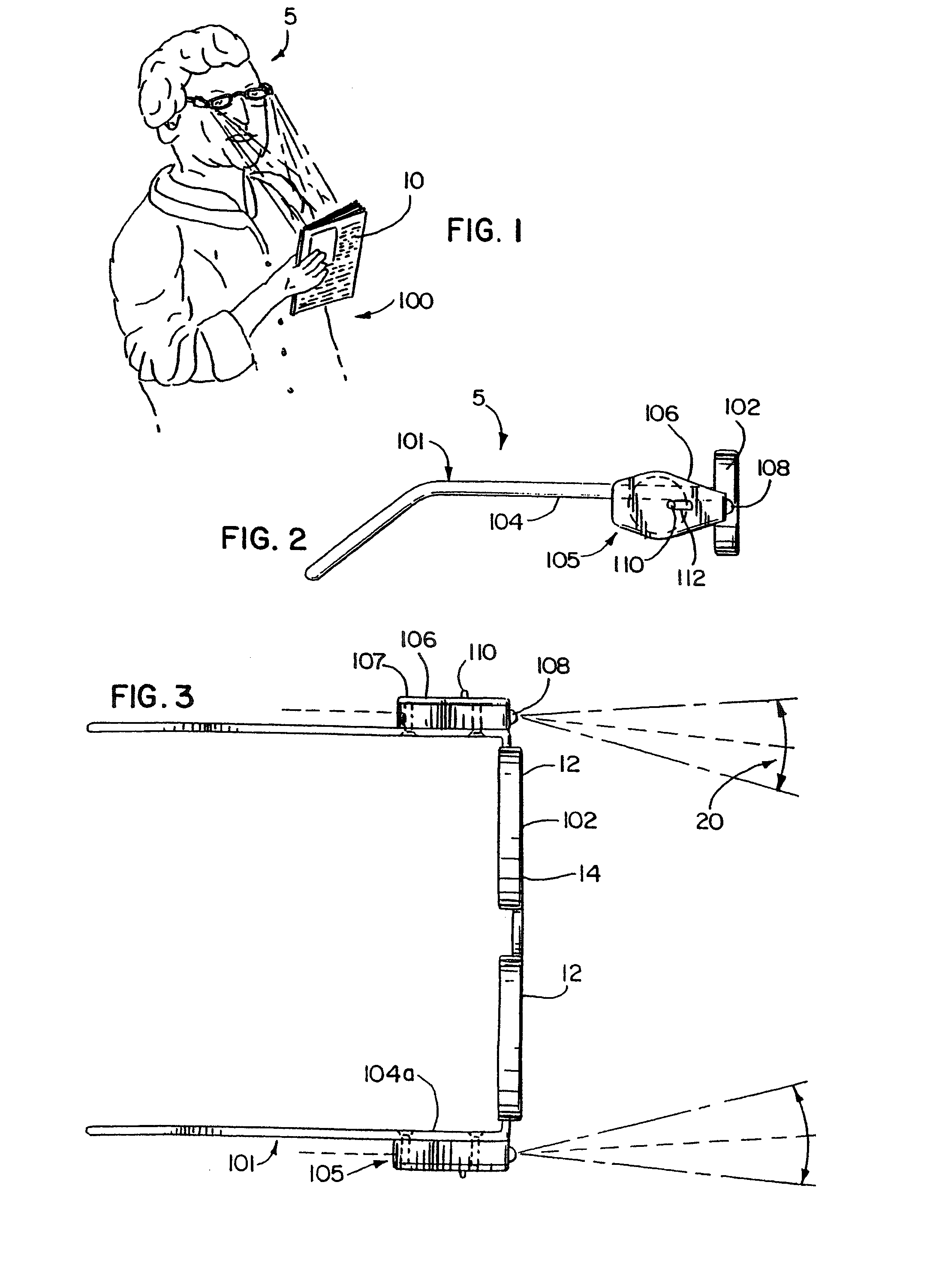
[0056]As shown in drawings for purposes of illustration, the invention is embodied in lighted reading glasses 5 which enable a user wearing the glasses 5 as shown in FIG. 1 to clearly read conventionally sized printed text 10, e.g. ten or twelve point font, held in a range of distances suitable for reading such text sizes where the reading is occurring in poorly or dimly lit areas. In this regard, the present lighted reading glasses 5 are ideally suited for use in areas that normally require a user to turn on a light before reading can occur but where doing so is less than desirable, such as in a car or when reading in bed with another present who is trying to sleep while you read.

[0057]The lighted glasses 5 which as stated above are preferably reading glasses 5 will include lenses 12 of light transmissive material configured to refract light to correct for defects in vision due to errors of refraction in the human eye and thus, at least one of the lens surfaces 14 will be curved to...


PUM


Abstract

A clip-on light apparatus is provided having a polyaxial coupling joint between a light module and frame to permit the light module to be pivoted about a plurality of axes relative to the frame for directing light in a plurality of directions. The polyaxial coupling joint preferably permits pivoting of the light module about at least two orthogonal axes. In one form, the light module is mounted to a pivot shaft about which the module can be turned with the pivot shaft itself being pivoted along one of the two orthogonal pivot axes.

Description

CROSS-REFERENCE TO RELATED APPLICATION[0001]This application is a continuation-in-part of prior application Ser. No. 10 / 571,796, filed Mar. 15, 2006, which is a national filing of International Application PCT / US02 / 35665, filed Nov. 7, 2002, which is a continuation-in-part of application Ser. No. 10 / 145,595, filed May 14, 2002, now issued U.S. Pat. No. 6,612,696, which is a continuation-in-part of prior application Ser. No. 10 / 006,919, filed Nov. 7, 2001, now issued U.S. Pat. No. 6,612,695, all of which are hereby incorporated herein by reference in their entirety.FIELD OF THE INVENTION[0002]The present invention relates generally to lighted devices and, more particularly, to lighted devices for being removably attached to a desired item.BACKGROUND OF THE INVENTION[0003]The use of lights and other illuminating devices with glasses are known. Generally, however, they have not been very well adapted for use with reading glasses. As is known, these types of glasses typically are not wo...

Claims


Application Information

Patent Timeline
Patent Type & Authority Patents(United States)
IPC IPC(8): G02C1/00A42B1/24A42B3/04G02C11/04
CPCF21V21/084G02C11/04F21V21/0885
Inventor WATERS, MICHAEL
Owner WATERS
Why Eureka
Try Eureka