Electric power steering device, and control method thereof

a technology of electric power steering and control method, applied in the direction of motor/generator/converter stopper, dynamo-electric converter control, instruments, etc., can solve the problem of excessive torque, corresponding delay in timing of preventing overcurrent, and less steering rotation speed

Active Publication Date: 2010-02-16
TOYOTA JIDOSHA KK
View PDF20 Cites 3 Cited by
  • Summary
  • Abstract
  • Description
  • Claims
  • Application Information

AI Technical Summary

Benefits of technology

[0007]It is an object of the invention to detect the stroke end strike at early timing and restrain the occurrence of excessive torque.
[0013]Therefore, when it is detected that the steering position has reached the stroke end, the upper limit of the target current value is set at the predetermined value, so that the overshoot of the current is restrained and the generation of excessive torque is prevented. Furthermore, by setting the upper limit of the target current value at the value of the actual current detected immediately before it is judged that the steering position has reached the stroke end, a minimum needed assist torque can be maintained without generating excessive assist torque. Therefore, it does not happen that the assist torque becomes excessively small and the steering torque that the driver needs to provide increases.
[0014]Generally, in the electric power steering device, the steering torque of the steering wheel is detected on the basis of the twist of the torsion bar. Therefore, when the stroke end is reached through a quick steering wheel operation, the inertia torque of the steering wheel twists the torsion bar so that the detected torque value increases. The increase in the detected torque increases the necessary assist torque. However, further torque generated in the state where the stroke end has been reached only presses a stopper, and is useless. However, in this aspect of the invention, the generation of useless torque can be avoided by setting the upper limit of the target current value at the actual current value detected immediately before it is judged that the steering position has reached the stroke end.
[0015]Furthermore, the electric power steering device may further include current restriction release means for releasing an upper limit value restriction of the target current provided by the upper limit value setting means if the target current value determined by the target current determination means becomes lower than a predetermined value when the target current value is restricted by the upper limit value setting means. For example, this predetermined value may be the upper limit value set by the upper limit value setting means. Therefore, the current restriction can be released at proper timing, and unnecessary current restriction can be prevented.
[0016]The restriction of the target current value by the upper limit value setting means or the judgment by the stroke end judgment means may be performed while the vehicle is at a stop, and do not need to be performed while the vehicle is running. During the running of the vehicle, the motor may sometimes be rotated by external force exerted on the wheel side from the road surface (so-called reverse input). In such a case, there is a risk of the stroke end judgment means making a false determination. In this aspect, however, by performing the judgment regarding the stroke end and the upper limit value restriction of the target current only while the vehicle is at a stop, the precision can be improved.

Problems solved by technology

Due to the influence thereof, the current through the motor rapidly increases, resulting in overshooting.
JP-A-11-78919, since the attainment of the stroke end is determined by detecting that the motor current has actually overshot, the determination is delayed, allowing excessively large torque to occur.
However, a situation where the steering rotation speed lessens occurs not only in the case where the stroke end is struck, but also in the case where the steering is held.
Therefore, the timing of preventing the overcurrent is correspondingly delayed.
However, if the determination regarding the stroke end is performed earlier, the likelihood of false detections increases.
Such a false detection leads to the reduction of the assist torque during the steering-held state, so that good steering assist cannot be obtained.

Method used


Image

  • Electric power steering device, and control method thereof
  • Electric power steering device, and control method thereof
  • Electric power steering device, and control method thereof

Examples


Embodiment Construction

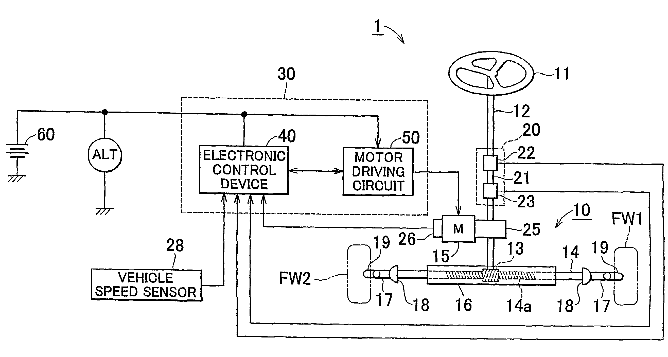
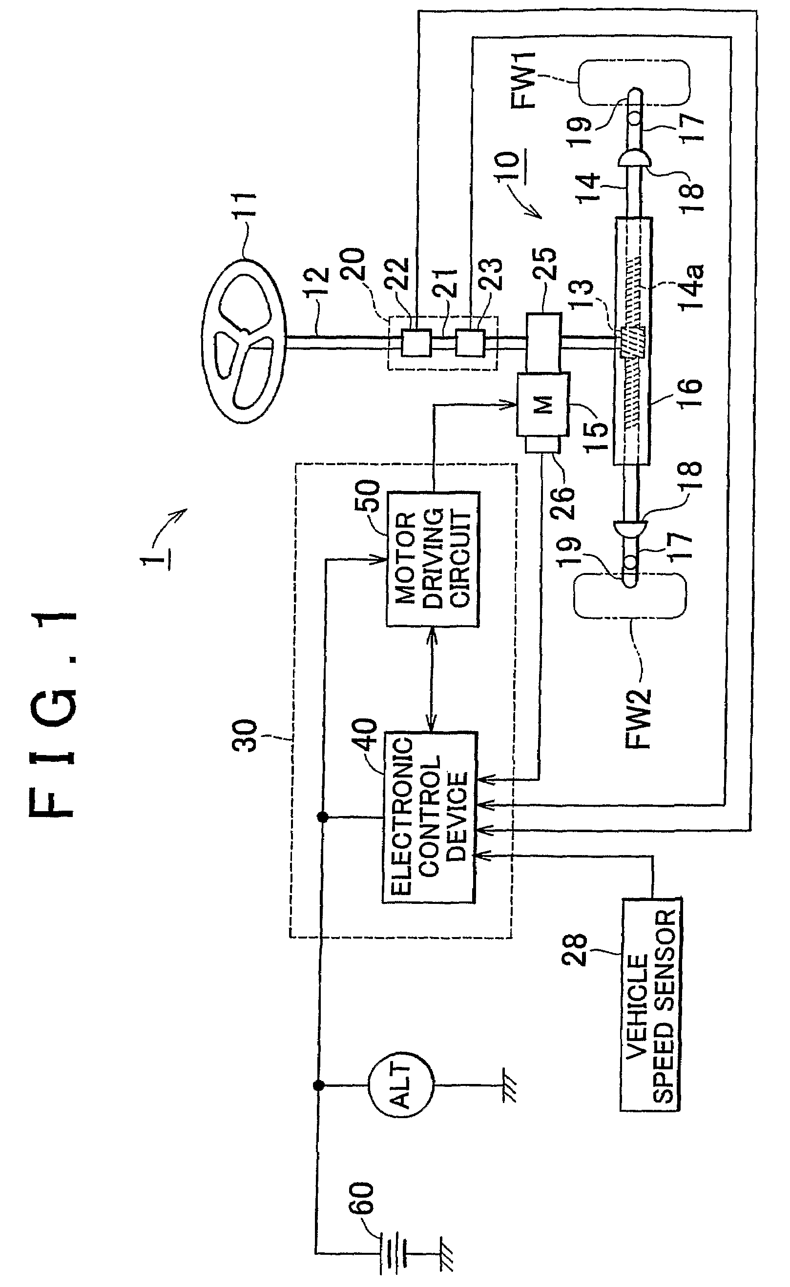
[0045]An electric power steering device in accordance with an embodiment of the invention will be described hereinafter through the use of the drawings. FIG. 1 schematically shows the electric power steering device in accordance with the embodiment.

[0046]The electric power steering device 1 is generally constructed of a steering assist mechanism 10 that gives steering assist force to the steering road wheels, and an assist control device 30 that drives and controls an electric motor 15 of the steering assist mechanism 10.

[0047]In the steering assist mechanism 10, axial rotation of a steering shaft 12 interlocked with the turning operation of the steering wheel 11 is converted into a motion of a rack bar 14 in a direction of its axis by a rack-and-pinion mechanism 13, and left and right front wheels FW1, FW2 that are the steering road wheels are steered in accordance with the motion of the rack bar 14 in the direction of its axis. As for the rack bar 14, a toothed portion 14a is hous...


PUM


Abstract

An actual detected current value and a target voltage value of an electric motor are subjected to a low-pass filter process, and amounts of change per time in the filtered actual current value and the filtered target voltage value are calculated. If the amount of change in the actual current value on the increase side is greater than a criterion value and the amount of change in the target voltage value on the decrease side is greater than a criterion value, it is judged that the stroke end has been reached. Then, the upper limit value of the target current value is set at the actual current value obtained in the immediately previous cycle of the feedback control, so as to prevent generation of unnecessary torque.

Description

BACKGROUND OF THE INVENTION[0001]1. Field of the Invention[0002]The invention relates to an electric power steering device that generates steering assist torque in accordance with the steering state of the steering wheel or handle, and a control method thereof.[0003]2. Description of the Related Art[0004]An electric power steering device has an assist controller that has a microcomputer in a main portion. Using the assist controller, the device controls the amount of electricity passed to an electric motor in accordance with the steering state of the steering wheel or handle so as to give a desired steering torque to a steering mechanism. For example, a steering torque sensor that detects the steering torque generated in association with the steering wheel operation of a driver and a vehicle speed sensor that detects the vehicle speed are connected to the assist controller. On the basis of the detection signals from the two sensors, the assist controller computes a target current va...

Claims


Application Information

Patent Timeline
Patent Type & Authority Patents(United States)
IPC IPC(8): H02P1/04
CPCB62D5/0469B62D5/04B62D6/00
Inventor YAMAZAKI, IPPEI
Owner TOYOTA JIDOSHA KK
Why Eureka
Try Eureka