
Quantitative calorimetry signal for sub-micron scale thermal analysis

a calorimetry signal and sub-micron scale technology, applied in the field of quantitative calorimetry for high-resolution thermal analysis, can solve the problems of lack of quantitative information, high localized surface effects, and inability to quantitatively measure the enthalpies of sthm techniques as practiced currently

Inactive Publication Date: 2010-02-23
KJOLLER KEVIN +1
View PDF1 Cites 6 Cited by
  • Summary
  • Abstract
  • Description
  • Claims
  • Application Information

AI Technical Summary

Benefits of technology

"The invention is a method and system for producing precise data on the temperature of a sample surface. The system includes a probe that can be heated and has a resistance monitored in real-time. The system can also scan the surface and measure the mass of any particles that stick to the probe. The method involves measuring the temperature and power of the probe in a clean condition, then measuring the probe with a particle attached, and subtracting the baseline data from the sample data. The system can also measure the resonant frequency of the probe and clean it to remove any particles. Overall, the invention allows for highly accurate and precise calorimetry data to be collected on sample surfaces."

Problems solved by technology

The heated probe will cause highly localized surface effects due to temperature.
The SThM technique as practiced currently does not allow quantitative measurements of the enthalpies.
The lack of quantitative information is due to the fact that the tip interaction with the surface from a heating standpoint has several inherently undefined parameters.
In particular, it is difficult to know how much of the sample's volume is heated, how uniformly is the heated volume affected, and what is the area available for heat flow from the tip to surface.
All of these factors contribute to the fact that heat flow from the tip into the bulk of the sample is not well-defined.
However since SThM does not measure enthalpy it does not on any scale provide the type of data available on bulk analysis systems such as the Differential Scanning Calorimetry (DSC) system.
Again because of the lack of knowledge of the quantity of material affected by the SThM it has not been possible to date to quantitatively determine the enthalpy absorbed by the sample or eg the enthalpy of fusion.
Examples include the determination of quartz in clays, which is difficult by other methods, and the analysis of polymer blends.

Method used


Image

  • Quantitative calorimetry signal for sub-micron scale thermal analysis
  • Quantitative calorimetry signal for sub-micron scale thermal analysis
  • Quantitative calorimetry signal for sub-micron scale thermal analysis

Examples


Embodiment Construction

[0020]It is assumed that one skilled in the art is familiar with the operation of a scanning probe microscope, and in particular, an atomic force microscope with a cantilever type probe. Such a microscope is the foundation for SThM. In the following description concepts such as scanning, imaging, and probe-sample interaction will be used with meanings known in the field of scanning probe microscopy, and only features pertinent to the novel techniques of the invention will be described in detail. It is also understood that most SPM's include a programmable control system allowing for a wide range of scanning, probe positioning, and deflection measurements which may be optimized for a particular application.

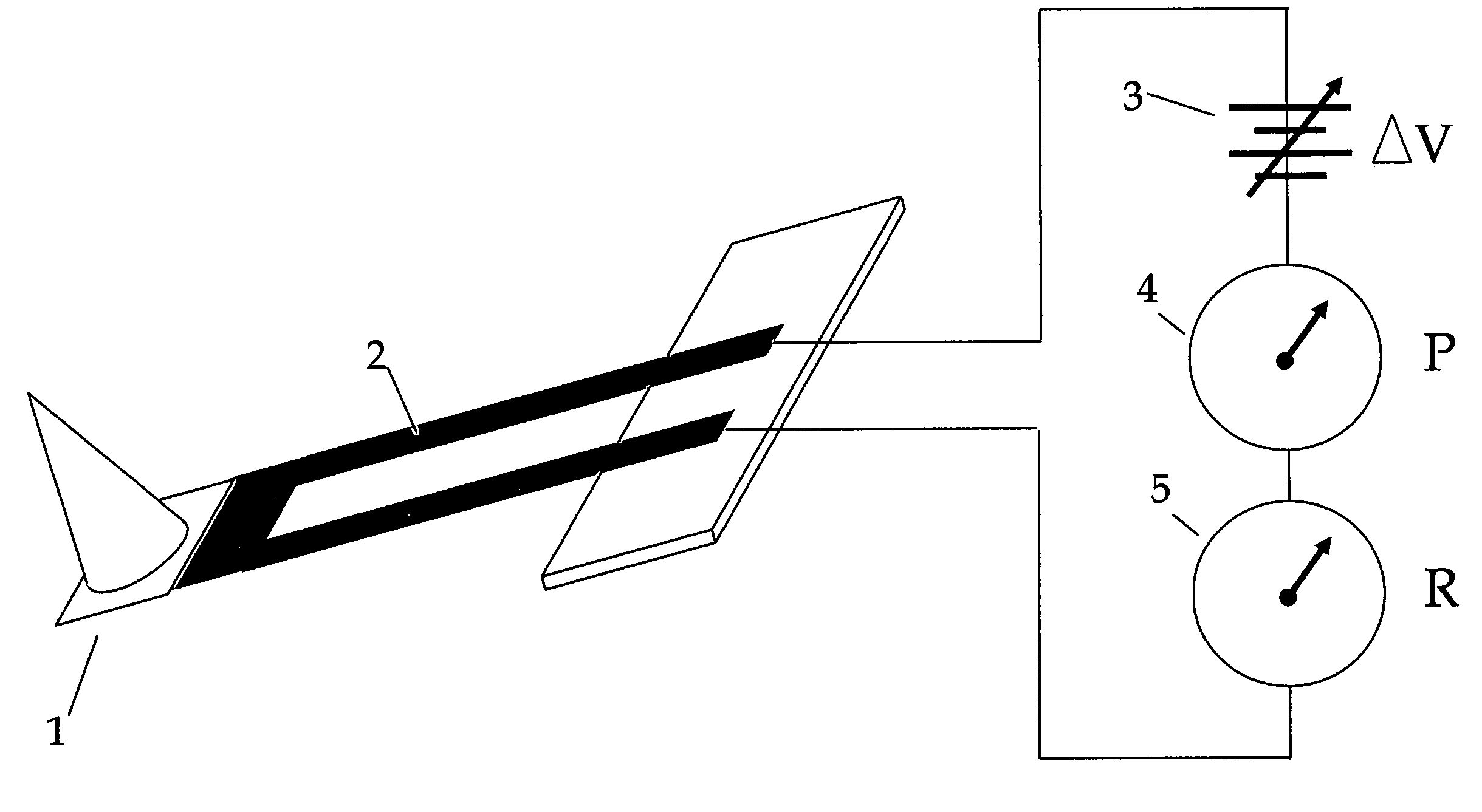
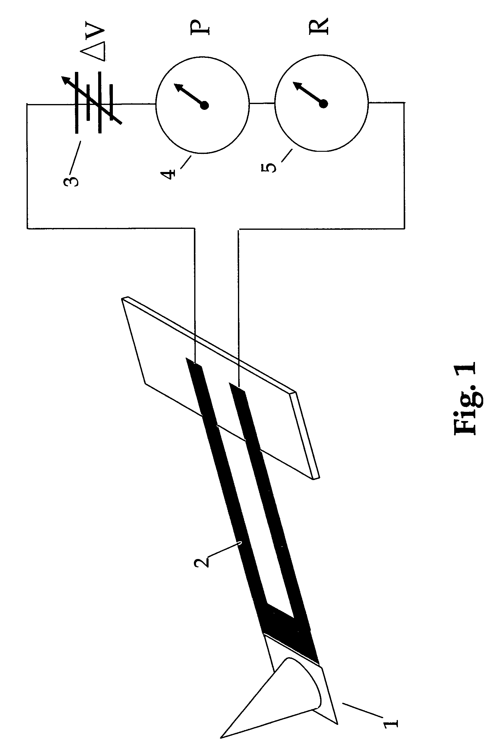
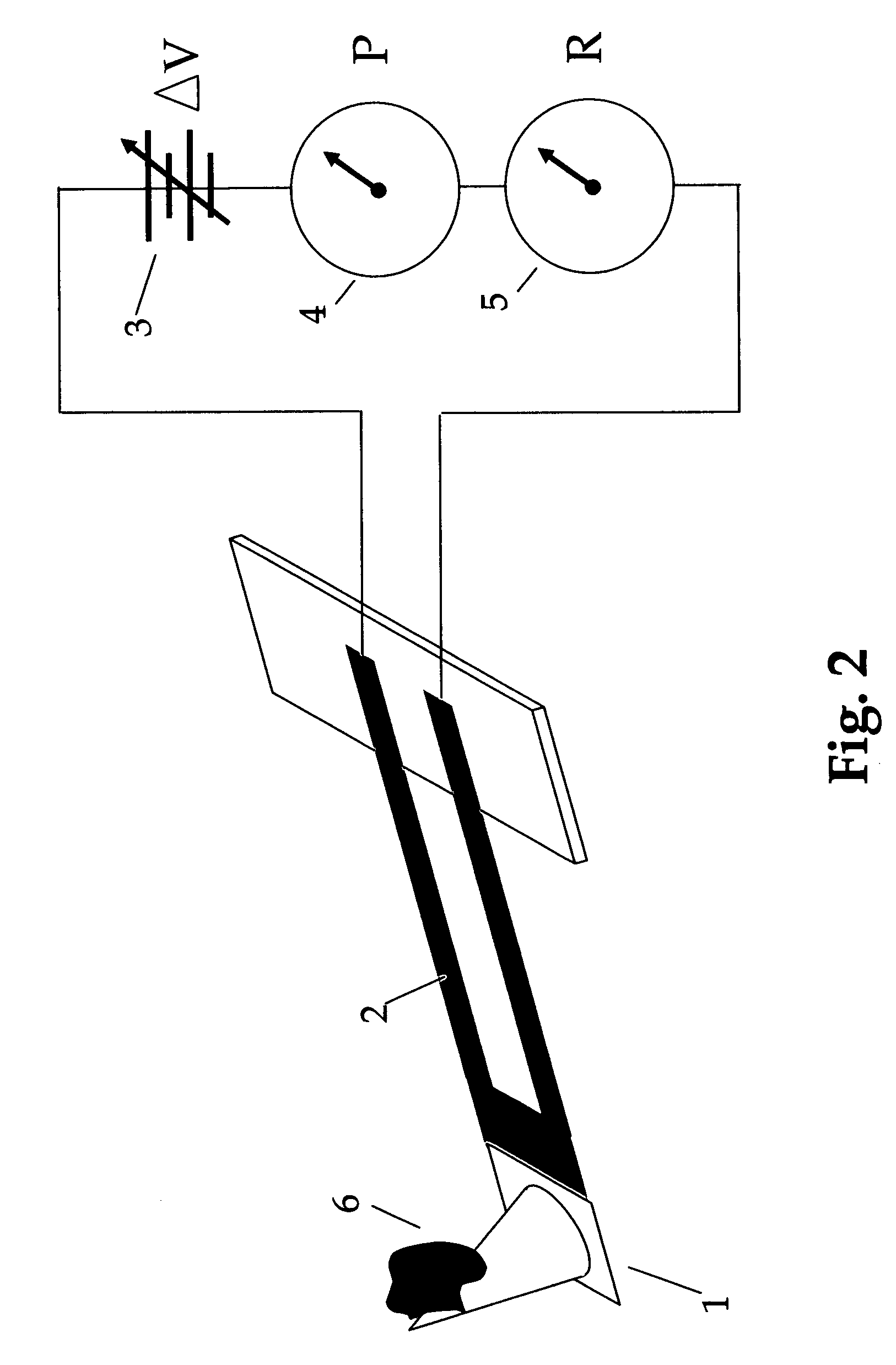
[0021]FIG. 1 shows a cantilever probe at 1. Only the probe is shown, and the scanning, deflection detection and other functional parts of the SThM are assumed. The probe has a heating resistive element 2. The probe with heater may be a bent wire type of probe known in the thermal m...


PUM

PropertyMeasurementUnit
resistanceaaaaaaaaaa
probe resistanceaaaaaaaaaa
temperatureaaaaaaaaaa

Abstract

The invention is a system and method for producing highly localized calorimetry data on a sample surface. The system is based on an SPM or other system with a probe and fine positioning capability. A heated probe is used to take a small sample (nano-sample) of a surface, and thereby make calorimetry measurements in a controlled manner.

Description

[0001]This application claims priority to U.S. provisional application Ser. No. 60 / 799,707, filed May 11, 2006.FEDERALLY SPONSORED RESEARCH / SEQUENCE LISTING[0002]Not ApplicableBACKGROUND OF THE INVENTION[0003]This invention relates to quantitative calorimetry for high resolution thermal analysis using probe based technology. For the purposes of clarity of this application, the reduction to practice has been explained using a Scanning Probe Microscope (SPM) but the technique described herein can be practiced with any device that can provide precise control of X, Y and Z motion of the probe, such as, by way of example, a micromanipulator.[0004]The family of thermal analysis techniques, collectively called micro-thermal analysis (micro-TA), has been in existence for nearly a decade now. Micro-TA methods are based on a scanning probe microscope in which the conventional passive probe, typically a cantilever arm with integral tip, is enhanced, typically by adding the capabilities to meas...

Claims


Application Information

Patent Timeline
Patent Type & Authority Patents(United States)
IPC IPC(8): G01K17/00G01Q10/00G01Q60/58
CPCG01Q60/58B82Y35/00
Inventor KJOLLER, KEVINHAMMICHE, AZZEDINE
Owner KJOLLER KEVIN
Learn More