
Gas burner for oven

a technology of gas burner and oven, which is applied in the direction of combustion process, heating fuel, application, etc., can solve the problems of limited thermal power, vibration and noise in the oven, mechanical energy of the combustion gas from the burner,

Inactive Publication Date: 2010-02-23
THIRODE GRANDES GUISINES POLIGNY
View PDF23 Cites 4 Cited by
  • Summary
  • Abstract
  • Description
  • Claims
  • Application Information

AI Technical Summary

Benefits of technology

"The patent describes a burner for a gas oven that has a flame retention device with a mesh that allows gas to pass through. The mesh has two main zones and a pilot zone that is thicker than the main zones. The pilot zone slows down the gas stream passing through it, creating a small flame that prevents the flame from blowing off. The burner also has an orifice for receiving secondary air, which helps to regulate the flow of combustion products and prevent hot spots. The main technical effects of this design are increased thermal output, improved flame stability, and reduced risk of flame blowing off."

Problems solved by technology

The mechanical energy of the combustion gases from the burner is a drawback, causing vibrations and noise in the oven.
One drawback of this type of burner is the limited thermal power.
A further drawback of this type of oven is that under the effect of the thermal variations and the mechanical effects of the combustion gas flow, the heating elements, brought to a high temperature, may start to vibrate.
This causes an unpleasant noise and reduces the lifespan of the oven.
However, this type of burner has the drawback of being restricted in the thermal output per cm2 of the retention plate.
The aforementioned drawback, namely that of increasing thermal energy solely at the point of the retention plate of the burner, is accentuated here, as the combustion gases are propagated radially relative to the axis of the burner.
The drawback with this type of burner is that, for limiting the combustion products which are not oxidised by combustion, it is necessary to introduce into the gas mixture, which passes through the burner, excess air relative to the stoichiometric proportions of the gas.
For a given thermal output of the burner, the over-supply of air may cause a detachment of the flame.
Even if the detachment of the flame is limited, however, the over-supply of air reduces the thermal output of the flame.

Method used


Image

  • Gas burner for oven
  • Gas burner for oven
  • Gas burner for oven

Examples


Embodiment Construction

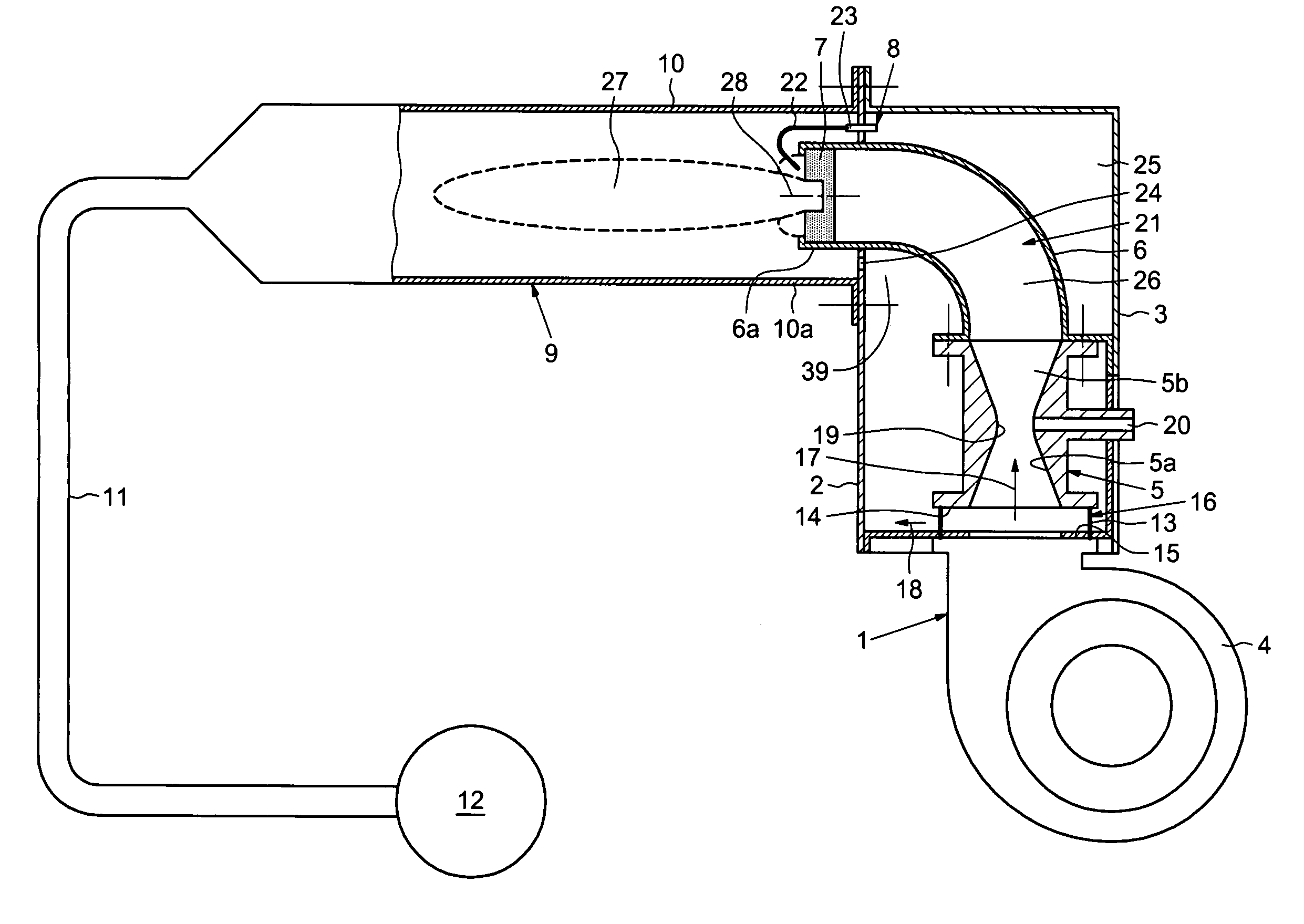
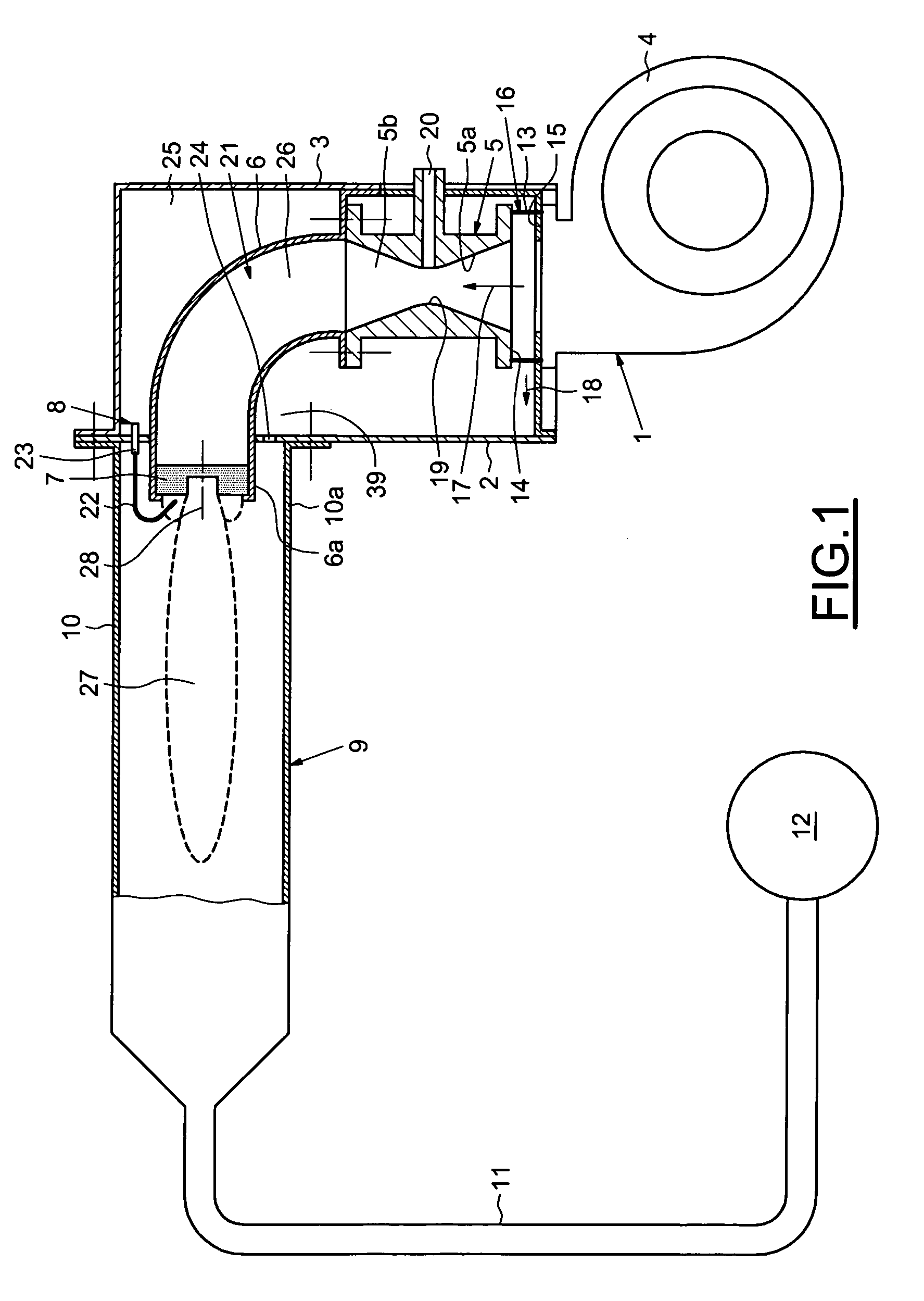
[0032]As illustrated in FIG. 1, a burner comprises a propulsive assembly 1 fixed to a fixing plate 2 and surrounded by a box 3. The propulsive assembly 1 comprises a fan 4, a venturi device 5, an upstream sleeve 6 and a retention device 7 for a flame 27. The fixing plate 2 also receives an ignition device 8 and a heat exchanger assembly 9. The heat exchanger assembly 9 successively comprises a combustion pipe 10 fixed to the fixing plate 2, at least one heat exchanger tube 11 and an outlet 12.

[0033]The fan 4 is of the centrifugal type and pushes the sucked-up air through the venturi device 5. The venturi device 5 is fixed rigidly opposite, and at a distance from, the outlet orifice of the fan 4. The bypass connecting device 16 comprises crosspieces 13, for example in the form of small pillars or washers which are pushed between an inlet plate 14 of the venturi device 4 and an outlet plate 15 of the fan 4. The mechanical connection between the venturi device 5 and the fan 4 is rigid ...


PUM


Abstract

Burner for gas oven comprising a device for retaining a flame of the burner, separating the flame from a mixing chamber capable of receiving a flow of primary air and gas to form a gaseous mixture. The flame retention device is provided with a mesh comprising metal threads, capable of allowing said gaseous mixture to pass through the mesh, said mesh comprising at least one main zone and a pilot zone which are adjacent. The pilot zone having, according to a main direction of the flame of the burner, a thickness greater than the thickness of the main zone, capable of slowing down the gaseous mixture passing through the pilot zone relative to the mixture passing through the main zone. The burner comprises at least one orifice capable of receiving a secondary air flow.

Description

BACKGROUND OF THE INVENTION[0001]1. Field of the Invention[0002]The invention generally relates to heating systems for ovens, particularly gas heating systems.[0003]2. Description of the Relevant Art[0004]In the field of gas burners for ovens, the ovens are used in large commercial or institutional kitchens.[0005]The energy produced by the combustion is recovered in thermal form. The products of the gas combustion pass through, for example, heat exchanger tubes where they are cooled to remove the thermal energy therefrom. Apart from possible pressure losses in the heat exchanger tubes or in chimney flues, the combustion gases from the burner are substantially at atmospheric pressure. The mechanical energy of the combustion gases from the burner is a drawback, causing vibrations and noise in the oven.[0006]A gas cooker fitted with hollow heating elements passed through by combustion products from a gas burner is known. One drawback of this type of burner is the limited thermal power....

Claims


Application Information

Patent Timeline
Patent Type & Authority Patents(United States)
IPC IPC(8): F23D14/14F23D14/02F23D14/12F23D3/40
CPCF23C3/002F23D14/08F23D14/26F24C3/087F23D2203/103F23D2900/00019
Inventor LECLERC, CHRISTOPHECORNU, GILBERTMICHAUD, DOMINIQUE
Owner THIRODE GRANDES GUISINES POLIGNY
Learn More