
Knee brace and methods of use and modification thereof

a technology of knee braces and knees, applied in the field of knee braces, can solve the problems of not being able to withstand significant side forces, originating laterally or medially, and being more susceptible to being shifted off its midline plane, and achieves the effects of not being able to easily adjust, reducing side load, and reducing side load

Inactive Publication Date: 2010-02-23
BROWN ALICE M
View PDF14 Cites 6 Cited by
  • Summary
  • Abstract
  • Description
  • Claims
  • Application Information

AI Technical Summary

Benefits of technology

The knee brace effectively relieves pain and prevents further damage by realigning the knee joint, potentially eliminating the need for invasive surgical procedures and allowing natural tracking of the patella, thus promoting recovery and strengthening of the surrounding muscles.

Problems solved by technology

Though it may appear to the casual observer as a simple joint, in actuality, it is extremely complex.
The knee joint 10 is designed to withstand generally large forces vertically, typically up to 400 pounds or more, however, it is not designed to withstand significant side forces, whether originating laterally or medially.
Unfortunately, the high degree of mobility of the knee joint 10 means it is more susceptible to being shifted off its midline plane 34 either laterally or more commonly, medially.
The shear load results in laterally opposite loads that are not desirable for normal operation of the knee joint 10.
This begins a vicious cycle in which the knee cartilage can be destroyed, and if left unchecked, the bones can be damaged.
In addition, scraping the underside of the patella 20 can result in further irritation, and thus, can eventually result in more chondromalacia being formed.
However, traditional knee braces are generally not effective in correcting the misalignment condition, or in lessening the pain associated therewith, since they typically apply equal and circumferentially uniform pressure on and around the knee joint 10 and the adjacent portions of both the lower and upper leg portions 14, 15.
Although these knee braces can be effective in restricting movement of the knee joint 10, they are largely ineffective in correcting a patello-femoral condition due to their application of equal and circumferentially uniform forces about the knee joint 10, and to their inability to realign misaligned femoral and tibial condyles.
Most of the less expensive knee braces are sleeve-type, which are generally both difficult to put on and uncomfortable after continued use.
In addition, sleeve-type braces made of neoprene inhibit heat dissipation and restrict the flow of blood to and from the knee joint 10, and thus, often result in swelling and pain.
This can result in further complications by allowing the muscles to be trained to move the knee joint 10 in an unnatural motion.
In addition, rigid side bar braces also prevent normal rotation of the femur 16 present in its normal 3-D path of movement, and thus, do not allow natural tracking of the knee joint 10.
Accordingly, they can also be ineffective in correcting a patello-femoral syndrome condition.
The wrap around knee braces presently available also apply equal and circumferentially uniform pressures on and around the knee joint 10, and thus, are equally ineffective in treating a patello-femoral syndrome condition.
Not only is this a complicated mechanism to apply, but it also attempts to correct a patello-femoral syndrome condition by applying a side force directly on the patella.
Though this may provide temporary relief to symptoms associated with the patello-femoral syndrome condition, it is not believed to be the best way to correct the source of the problem associated with the condition, which is misalignment of the femoral condyles relative to the meniscus and tibial condyles, and not misalignment of the patella.

Method used


Image

  • Knee brace and methods of use and modification thereof
  • Knee brace and methods of use and modification thereof
  • Knee brace and methods of use and modification thereof

Examples


Embodiment Construction

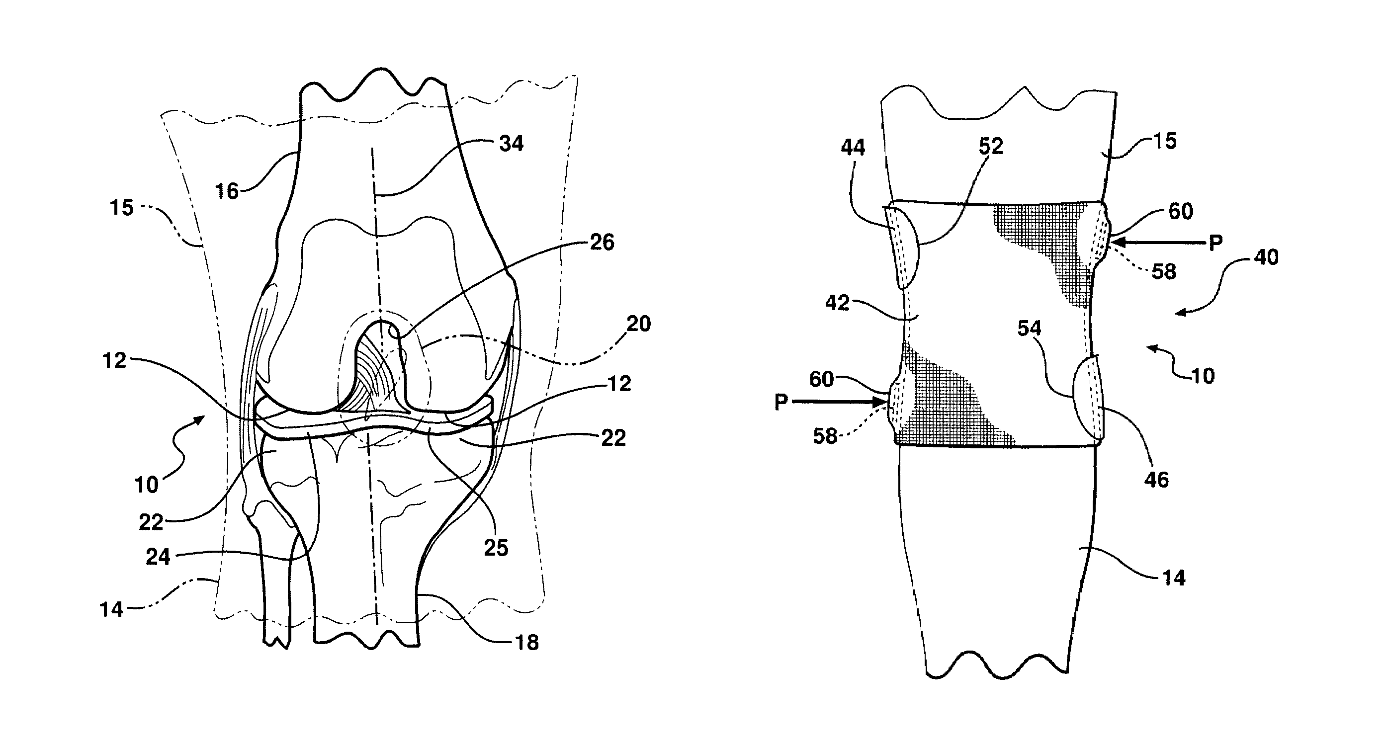
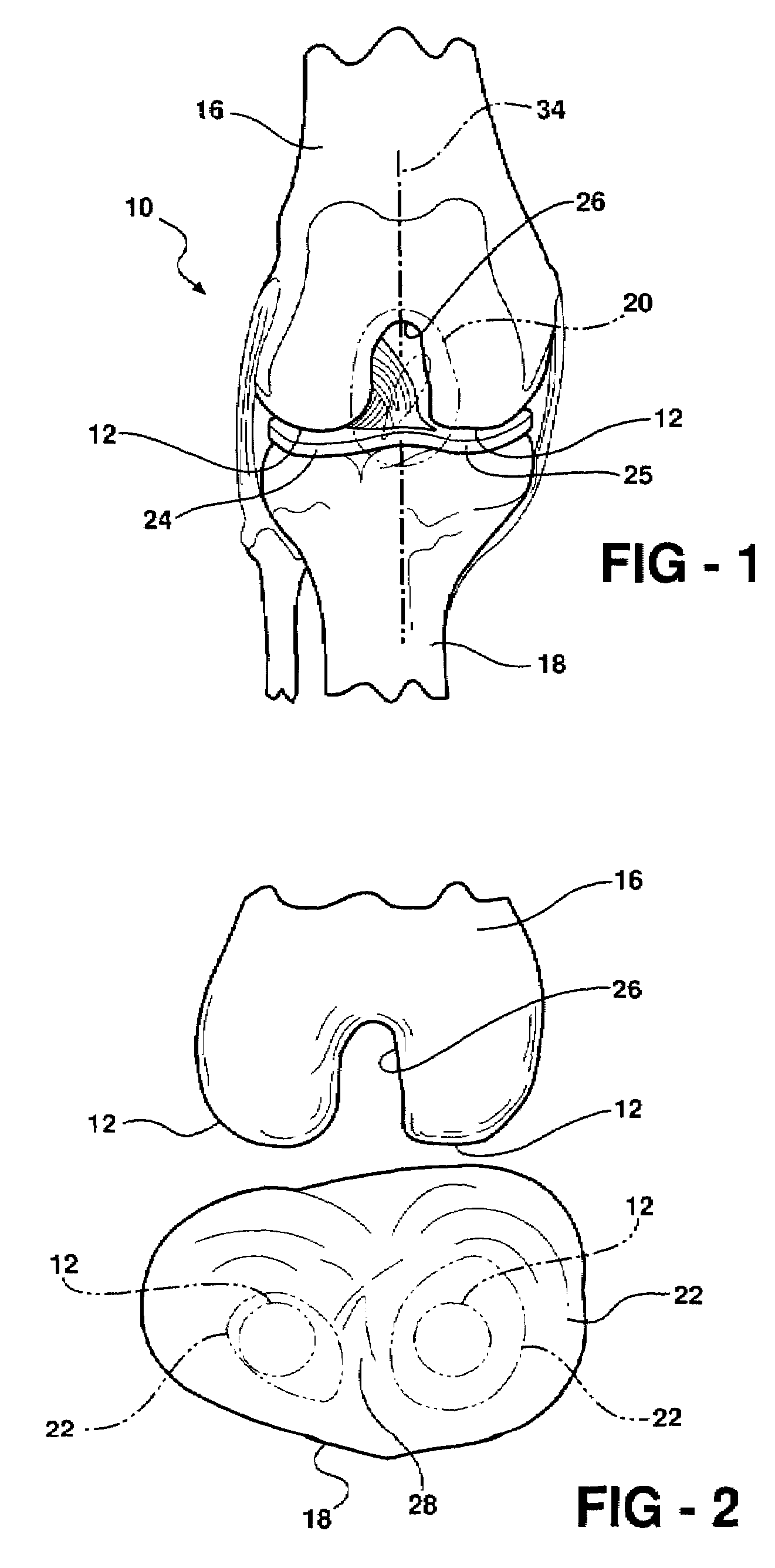
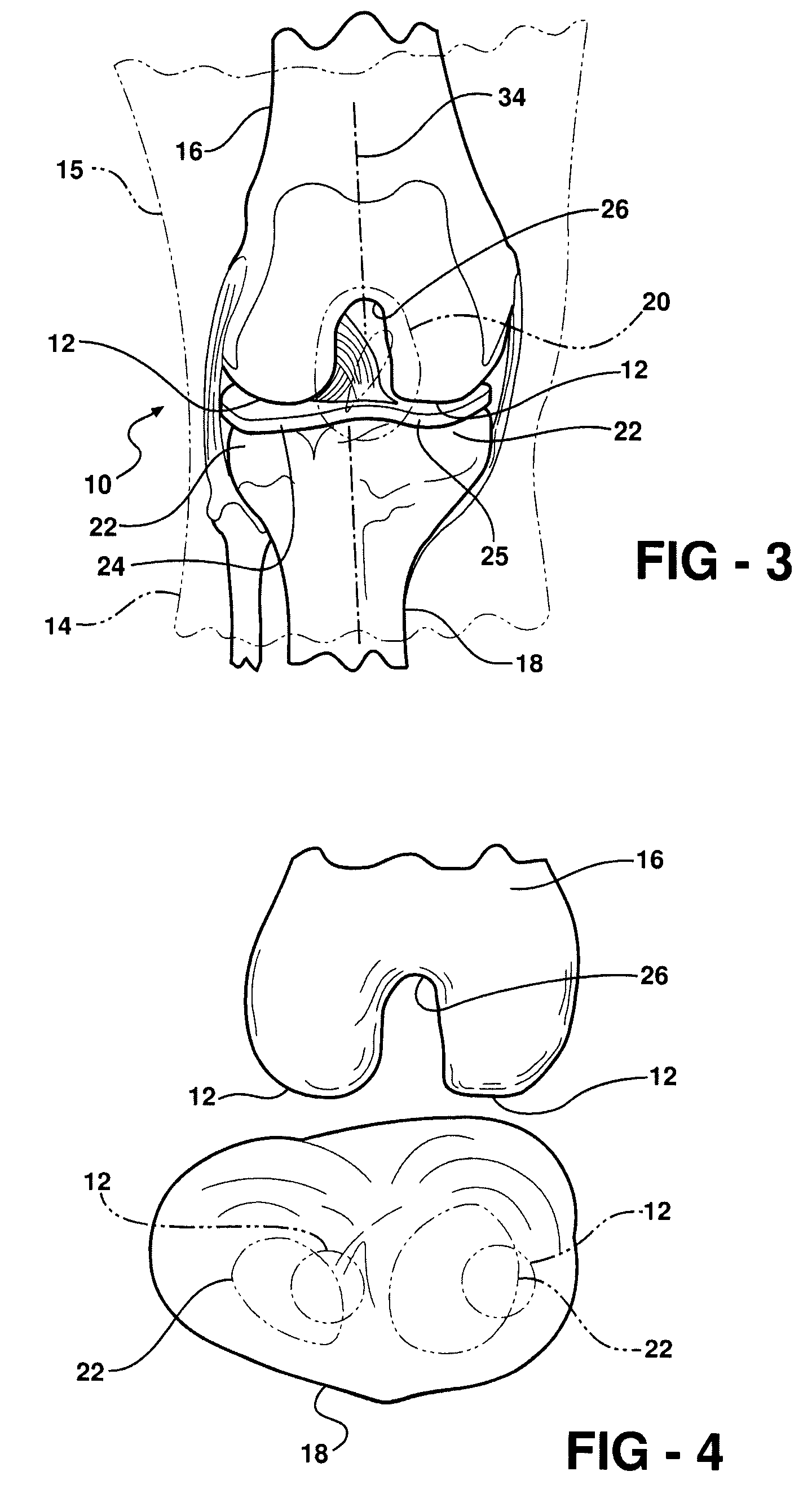
[0044]Referring in more detail to the drawings, FIGS. 8-12 show a four-way knee brace 40 constructed according to one embodiment of the invention for imparting corrective shear or side loads resulting in corresponding side pressures above and below the knee joint 10 of a user. The knee brace 40 is adjustable to apply the appropriate magnitude of side forces in the respective lateral and medial directions above and below the knee joint 10 simultaneously to correct a condition of patello-femoral syndrome. The side forces applied opposite one another above and below the knee joint 10 realign the misaligned femoral and tibial condyles 12, 22 relative to one another, and in proper alignment with the meniscus 24 (FIG. 7) therebetween. Accordingly, the knee brace 40 relieves any discomfort typically associated with the patello-femoral condition, while also preventing potential or additional damage to the knee joint 10. As such, the knee brace 40 provides a noninvasive, economical mechanism...


PUM


Abstract

A knee brace, method of use thereof, and modification to an existing knee brace facilitates inducing side loads to a knee joint to align upper and lower leg portions relative to one another, thereby allowing the knee joint to function properly over its full dynamic range of motion. The knee brace, whether as manufactured or modified, acts to apply a lateral shear force to the knee joint through application of opposing lateral forces, with one lateral force being above the knee joint in one direction and the other lateral force being below the knee joint in an opposite direction. The counteracting forces act to shift femoral condyles and tibial condyles of the knee joint back into proper lateral alignment without acting directly on the patella to counteract the effects of the patella femoral syndrome.

Description

CROSS-REFERENCE TO CO-PENDING APPLICATION[0001]This patent application claims priority to U.S. Provisional Patent Application Ser. No. 60 / 771,062, filed Feb. 7, 2006, which is hereby incorporated herein by reference in its entirety.BACKGROUND OF THE INVENTION[0002]1. Technical Field[0003]This invention relates generally to knee braces, and more particularly to knee braces worn externally about a knee joint for supporting and manipulating the knee joint.[0004]2. Related Art[0005]As is known, and shown in FIGS. 1 and 2, a knee joint 10 is the largest joint in the body and has a unique anatomy due to its unusual movement. Though it may appear to the casual observer as a simple joint, in actuality, it is extremely complex. The complexity results from the fact that the knee joint 10 has femoral condyles 12 that rotate downward and slightly medial with each flexion of a lower leg portion, then rotate slightly backward and upward with the extension of a lower leg portion 14 relative to an ...

Claims


Application Information

Patent Timeline
Patent Type & Authority Patents(United States)
IPC IPC(8): A61F5/00A41D13/00A61F13/00A61F13/06
CPCA61F5/0106
Inventor BROWN, ALICE M.
Owner BROWN ALICE M
Learn More