
Portable terminal having antenna apparatus

a portable terminal and antenna technology, applied in the field of antenna apparatus and portable terminals, can solve the problems of reducing the space available for bluetooth apparatus and other elements on the printed circuit, reducing the function the spatial utilization degree of the printed circuit board 104 is not optimal, so as to prevent the function lowering of the portable terminal, enhance the function, and enhance the spatial utilization degree and design freedom degree of the printed circuit board.

Inactive Publication Date: 2010-02-23
LG ELECTRONICS INC
View PDF2 Cites 0 Cited by
  • Summary
  • Abstract
  • Description
  • Claims
  • Application Information

AI Technical Summary

Benefits of technology

The present invention provides an antenna apparatus that can improve the utilization of space and design freedom of a printed circuit board by reducing the non-ground region. It also prevents a decrease in function of a portable terminal. Additionally, the antenna apparatus can be installed at the edge of the printed circuit board to enhance its function and prevent interference. The invention includes a matching stub and antenna electrically connected to it, with hole ground pads used as the matching stub. The non-ground region with the ground removed for mounting the antenna apparatus can be formed at the edge of the printed circuit board. The matching stub can be implemented by electrically connecting one of the hole ground pads to the antenna as a non-ground state. The hole ground pads can consist of a first pad used as the matching stub with a non-grounded state, and a second pad separated from the first pad and used as the hole ground pad by being grounded.

Problems solved by technology

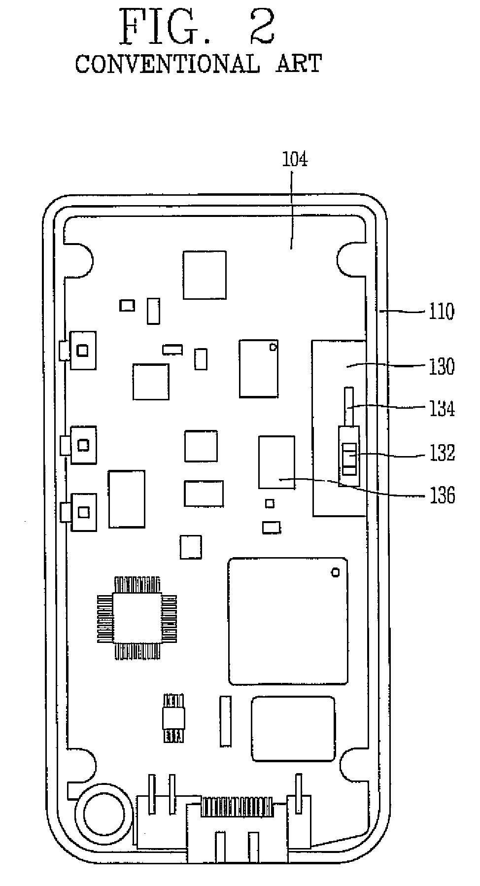
However, this reduces the amount of available space for the Bluetooth apparatus and other elements on the printed circuit board 104 and thus a spatial utilization degree of the printed circuit board 104 is not optimal.
Furthermore, in the related art portable terminal, since the amount of non-ground region 130 is relatively large, the amount of ground region is relatively small, which thereby decreases the function of the portable terminal.
This degrades the formation of a desired signal emission pattern, thereby degrading the function of the Bluetooth antenna.

Method used


Image

  • Portable terminal having antenna apparatus
  • Portable terminal having antenna apparatus
  • Portable terminal having antenna apparatus

Examples


first embodiment

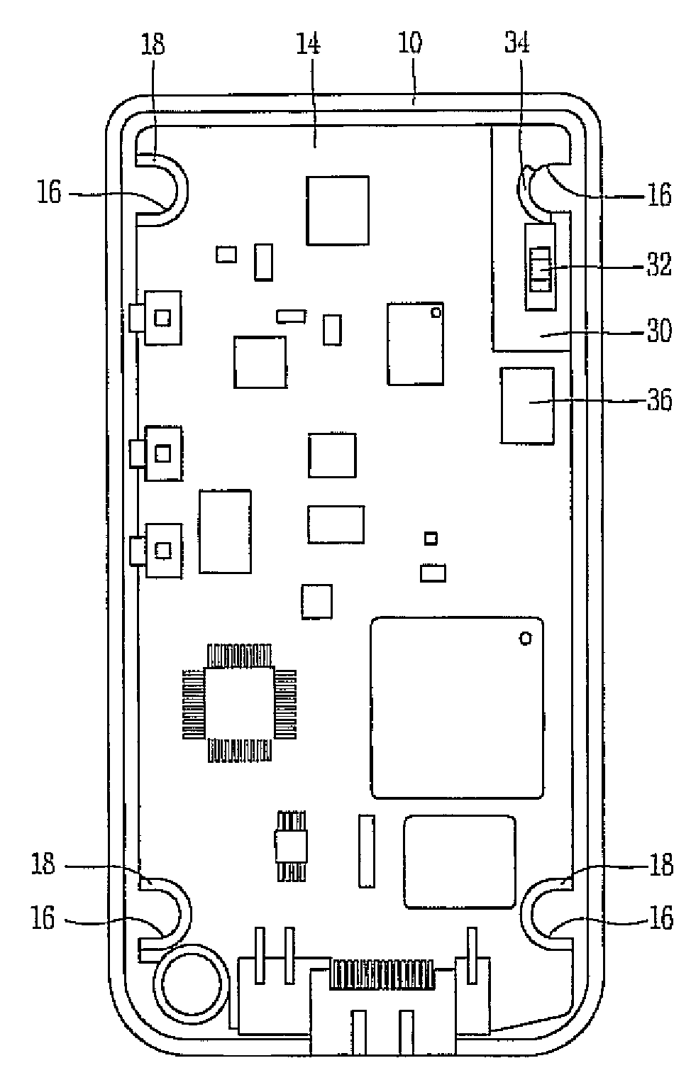
[0026]FIG. 3 is a perspective view showing a portable terminal having an antenna apparatus according to the present invention, and FIG. 4 is a frontal view showing a printed circuit board having a antenna apparatus according to the present invention.

[0027]The portable terminal according to the present invention may comprise a terminal body 10 (housing, frame, etc.) having a key pad 12 (and / or other types of user input devices such as a touch-sensitive screen, click wheel, function buttons, etc.) for inputting information at a front surface and having a printed circuit board (PCB) 14 (or other type of substrate) on which circuit components are mounted; a display unit 20 (including a graphics processor, image processing circuitry, etc.) having a display 22 (screen, LCD, OLED, etc.) mounted on the terminal body 10 for displaying information; and an antenna apparatus mounted at the printed circuit board 14.

[0028]A screw notch 16 (e.g., a screw-coupling hole or other attachment opening, ...

second embodiment

[0034]The exemplary embodiments of the present invention (as shown in the Figures) have four hole ground pads 18, one at each of the four corners of the PCB 14. It has been found that using one of these hole ground pads to function as a matching stub 34 for the antenna 32 does not detrimentally effect the overall grounding needed for the portable terminal. Namely, the remaining hole ground pads 18 (e.g., three shown in the Figures) provide adequate grounding for the portable terminal. Alternatively, a fourth hole ground pad 42 (as in the second embodiment shown in FIG. 5) that is separated from the matching stub 40 may be provided.

[0035]The matching stub 34 may be formed at a periphery region of the screw notch 16 formed at the printed circuit board 14 as a semicircular ridge shape (i.e., curved shoulder, bent protrusion, etc.), and is electrically connected to the antenna 32. Other appropriate shapes and configurations for the matching stub 34 are possible.

[0036]Accordingly, as one...


PUM


Abstract

A wireless communication device comprising a substrate, an antenna unit mounted on the substrate, and multiple conductive pads at one or more periphery regions of the substrate, one conductive pad among the multiple conductive pads being connected with and providing impedance matching to the antenna unit.

Description

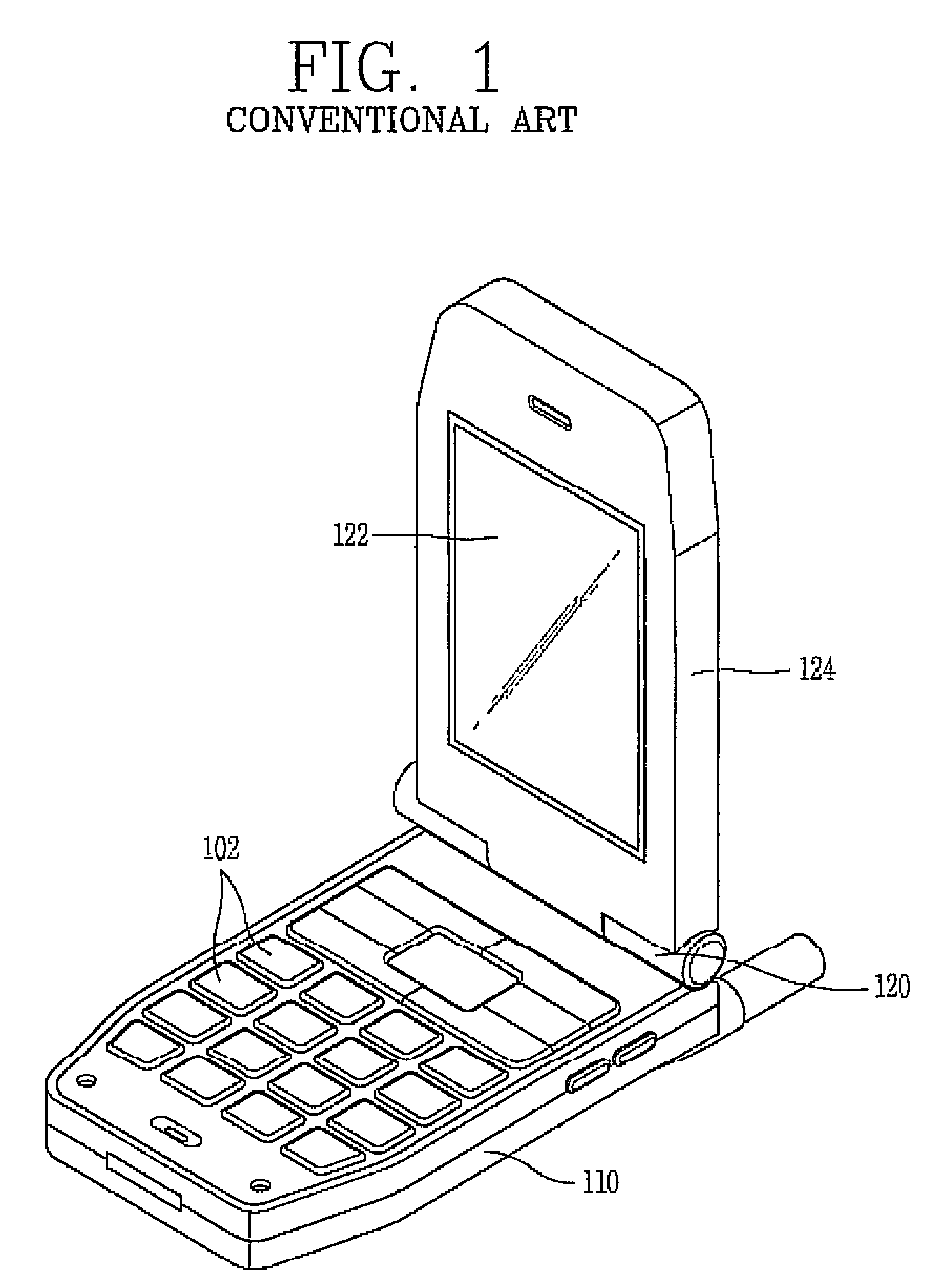
CROSS-REFERENCE TO RELATED APPLICATIONS[0001]Pursuant to 35 U.S.C. § 119(a), this application claims the benefit of earlier filing date and right of priority to Korean Application No. 10-2005-0068081, filed on Jul. 26, 2005, the contents of which is hereby incorporated by reference herein in its entirety.BACKGROUND[0002]1. Field of the Invention[0003]The present invention relates to an antenna apparatus and a portable terminal having the same, and more particularly, to an antenna apparatus capable of having an enhanced antenna function with minimal installation space, and a portable terminal having the same.[0004]2. Description of the Background Art[0005]A Bluetooth apparatus allows short-range wireless communication between electronic devices (e.g., a computer, a portable terminal, home appliances, etc.), and is generally installed in a portable terminal (e.g., mobile phone, PDA, etc.).[0006]FIG. 1 is a perspective view showing a portable terminal having a Bluetooth apparatus in ac...

Claims


Application Information

Patent Timeline
Patent Type & Authority Patents(United States)
IPC IPC(8): H01Q1/24H01Q9/16
CPCH01Q1/242H01Q1/243H05K1/0215H05K1/0243H05K1/0213H05K1/181H05K3/325H05K2201/10409H04B1/40H01Q1/24H04W84/18
Inventor LEE, HYOK
Owner LG ELECTRONICS INC
Learn More