
Bearing assembly and spindle motor including the same

a bearing assembly and spindle motor technology, applied in the direction of sliding contact bearings, instruments, record information storage, etc., can solve the problems of deteriorating the performance and a lifespan of the spindle motor, and the function of the circulation hole. to prevent the function of the circulation par

Inactive Publication Date: 2013-08-01
SAMSUNG ELECTRO MECHANICS CO LTD
View PDF4 Cites 2 Cited by
  • Summary
  • Abstract
  • Description
  • Claims
  • Application Information

AI Technical Summary

Benefits of technology

The present invention provides a bearing assembly and a spindle motor with a circulation part that prevents the adhesive from being introduced into the circulation part and maintaining the function of the circulation part. The bearing assembly includes a sleeve and a sleeve housing surrounding the sleeve to prevent leakage of oil, and at least one circulation part formed such that upper and lower surfaces of the sleeve and the sleeve housing are in communication with each other. The technical effects include preventing deformation of the circulation part and maintaining the function of the bearing assembly.

Problems solved by technology

However, in this process, the adhesive may be introduced into a circulation hole for controlling pressure to thereby deteriorate a function of the circulation hole.
As a result, a predetermined region of the circulation hole is blocked by the adhesive to cause a defect in functions of adjusting internal pressure of the spindle motor and discharging air bubbles, thereby deteriorating performance and a lifespan of the spindle motor.
According to Patent Document 1, mentioned in the following Related Art Document, there is still a problem in that, in the case of coupling a sleeve and a sleeve housing to each other with an adhesive, the adhesive may be introduced into a circulation hole to thereby deteriorate a function of the circulation hole.

Method used


Image

  • Bearing assembly and spindle motor including the same
  • Bearing assembly and spindle motor including the same
  • Bearing assembly and spindle motor including the same

Examples


first embodiment

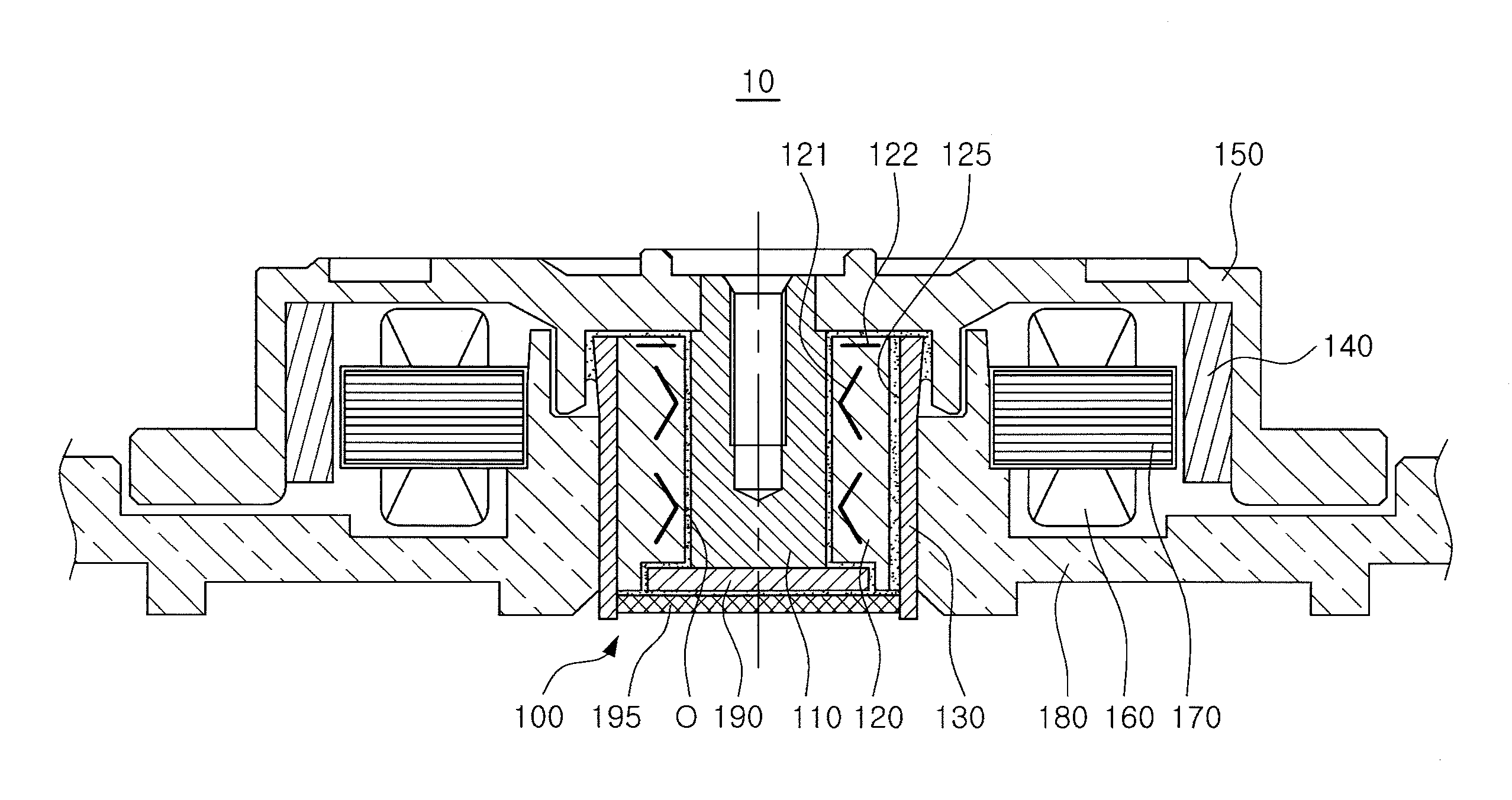
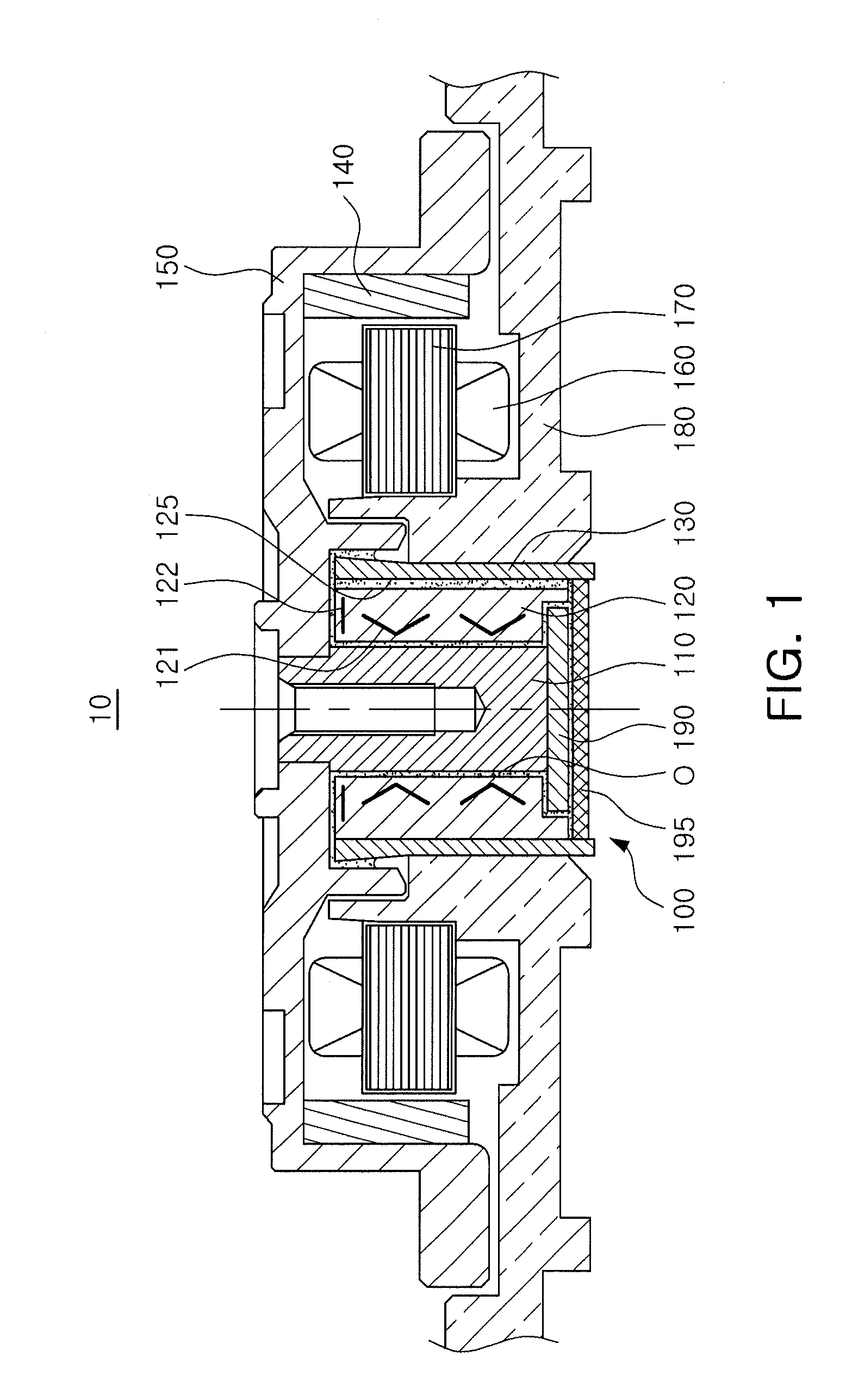
[0043]Referring to FIGS. 1 through 4, a spindle motor 10 including a bearing assembly 100 according to the present invention may include the bearing assembly 100 including a sleeve 120 and a sleeve housing 130, a hub 150 having a magnet 140 coupled thereto, and a base 180 including a core 170 having a coil 160 wound therearound.

[0044]Terms with respect to directions will be first defined. As viewed in FIG. 1, an axial direction refers to a vertical direction based on the shaft 110, and an outer diameter or inner diameter direction refers to a direction towards an outer edge of a hub 150 based on the shaft 110 or a direction towards a center of the shaft 110 based on the outer edge of the hub 150.

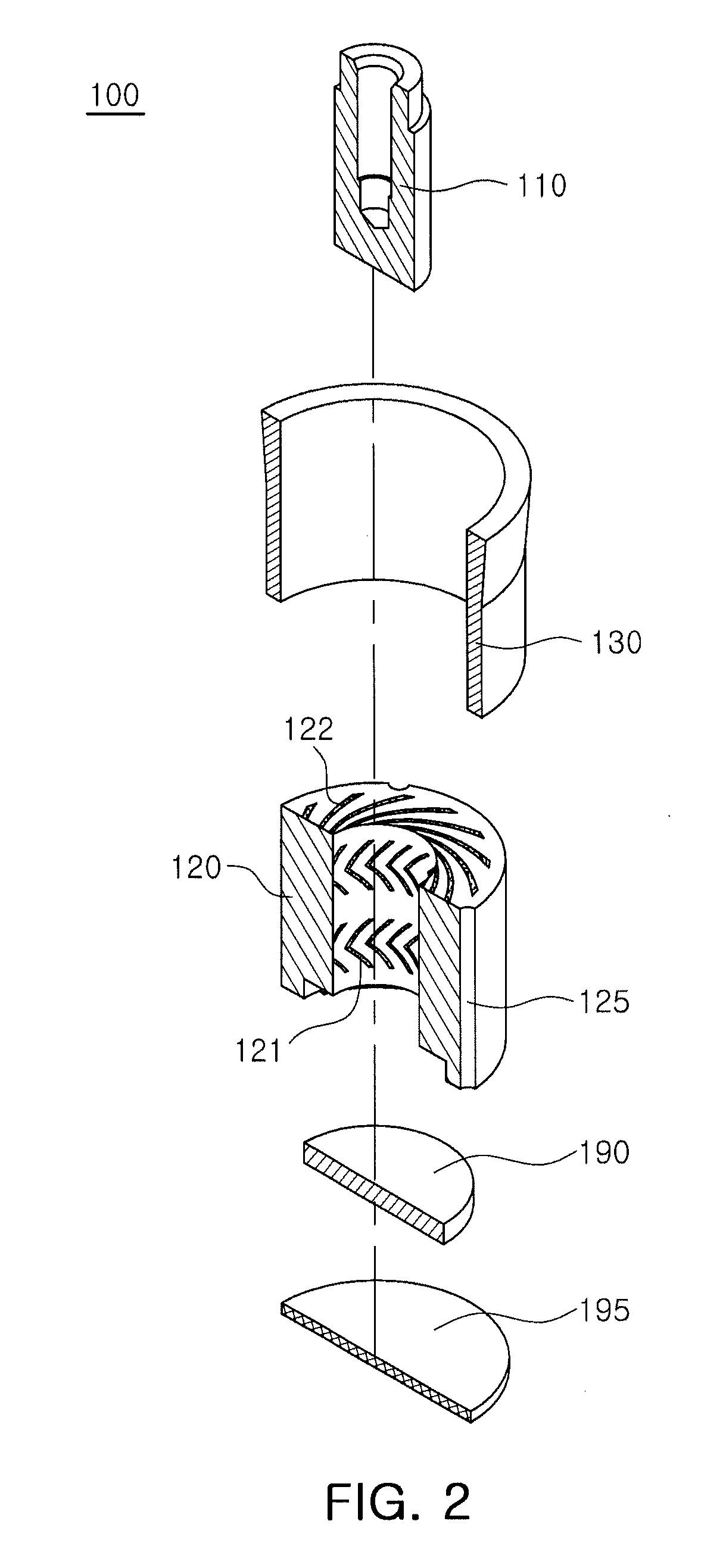
[0045]The bearing assembly 100 may include the sleeve 120 supporting the shaft 110 and the sleeve housing 130 surrounding the sleeve 120, wherein at least one of the sleeve 120 and the sleeve housing 130 may include at least one circulation part 125.

[0046]The sleeve 120 is a component suppor...

second embodiment

[0080]FIG. 5 is a schematic plan view showing a sleeve and a sleeve housing provided in a bearing assembly according to the present invention.

[0081]Referring to FIG. 5, a sleeve 220 provided in the bearing assembly according to the second embodiment of the present invention may include at least one circulation part 225, which may have the same configuration and effect as those of the circulation part 125 described with reference to FIGS. 1 through 4.

[0082]Here, an inner peripheral surface of a sleeve housing 230 may have a variable radius of curvature. More specifically, the inner peripheral surface of the sleeve housing 230 may have a radius of curvature larger at a portion corresponding to a boundary between the circulation part 225 and an outer side of the circulation part 225, than at a portion corresponding to the outer side of the circulation part 225.

[0083]In other words, the radius of curvature of the inner peripheral surface of the sleeve housing 230 may gradually increase ...

third embodiment

[0085]FIG. 6 is a schematic plan view showing a sleeve and a sleeve housing provided in a bearing assembly according to the present invention.

[0086]Referring to FIG. 6, a sleeve housing 330 provided in the bearing assembly according to the third embodiment of the present invention may include at least one circulation part 335, which may be formed by being depressed from an inner peripheral surface of the sleeve housing 330 such that upper and lower surfaces of the sleeve housing 330 are in communication with each other.

[0087]Here, the circulation part 335 may be symmetrical based on the center of rotation of the shaft 110 and serve as a circulation hole after the sleeve housing 330 and a sleeve 320 are coupled to each other.

[0088]Meanwhile, the inner peripheral surface of the sleeve housing 330 may have a maximum radius of curvature at a portion adjacent to the circulation part 335 and gradually increase toward the circulation part 335.

[0089]Therefore, a space filled by the adhesive...


PUM


Abstract

There is provided a bearing assembly including: a sleeve supporting a shaft via oil; a sleeve supporting a shaft via oil; a sleeve housing surrounding the sleeve to prevent leakage of the oil; and at least one circulation part formed such that upper and lower surfaces of at least one of the sleeve and the sleeve housing are in communication with each other, wherein at least one of an outer peripheral surface of the sleeve and an inner peripheral surface of the sleeve housing has a maximum radius of curvature at a portion adjacent to the circulation part.

Description

CROSS-REFERENCE TO RELATED APPLICATIONS[0001]This application claims the priority of Korean Patent Application No. 10-2012-0008059 filed on Jan. 27, 2012, in the Korean Intellectual Property Office, the disclosure of which is incorporated herein by reference.BACKGROUND OF THE INVENTION[0002]1. Field of the Invention[0003]The present invention relates to a bearing assembly and a spindle motor including the same, and more particularly, to a motor capable of being used in a hard disk drive (HDD) for rotating a recording disk.[0004]2. Description of the Related Art[0005]A hard disk drive (HDD), an information storage device, reads data stored on a disk or writes data to a disk using a read / write head.[0006]The hard disk drive requires a disk driving device capable of driving the disk. In the disk driving device, a small-sized spindle motor is used.[0007]In the small-sized spindle motor, a fluid dynamic bearing has been used. The fluid dynamic bearing is a bearing in which a shaft, a rot...

Claims


Application Information

Patent Timeline
IPC IPC(8): F16C32/06H02K7/08
CPCH02K5/1675H02K7/085F16C33/1085F16C17/107F16C33/107F16C2370/12H02K5/16G11B19/20
Inventor KIM, HAN BYULLEE, IK SUNKIM, JU HO
Owner SAMSUNG ELECTRO MECHANICS CO LTD
Learn More