Method of calibrating an ophthalmic-lens-piercing machine, device used to implement one such method and ophthalmic-lens-machining apparatus comprising one such device

a technology of ophthalmic lenses and machining equipment, which is applied in the direction of testing/calibration of speed/acceleration/shock measurement devices, electrical measurements, structural/machine measurements, etc., can solve the problems of low accuracy of offset measurement (of the order of a 10th of a millimeter), and the operation is not easy to carry out, and achieves simple manipulation operations. , the effect of increasing the accuracy

Active Publication Date: 2010-02-23
LUNEAU TECH OPERATIONS
View PDF7 Cites 9 Cited by
  • Summary
  • Abstract
  • Description
  • Claims
  • Application Information

AI Technical Summary

Benefits of technology

[0021]The object of the invention is to propose a calibration method of the type described above, making it possible to obtain a marked increase in accuracy, and requiring a shorter operating time and markedly simpler manipulation operations. This object is achieved by a calibration method according to the invention, in which the following steps are executed in succession. First an image of the previously drilled template is created. the image is analyzed by image analysis unit, so as to measure the offset between the position of the real drilling point and the position of the target point; and the guidance unit is programmed so as to introduce a correction of the command coordinates capable of compensating for the offset.

Problems solved by technology

This is due, in particular, to the inaccuracy, even if very small, of the positioning of the adapter on the lens, and the inaccuracy of the fixing of the adapter to the support 2, resulting, for example, from the manufacturing tolerances of these parts and from the possible deformation of the adapter during the preliminary grinding operation.
This method has two principal drawbacks, namely the low accuracy of the measurement of the offset (of the order of a 10th of a millimeter), and the considerable time taken for the operation.

Method used


Image

  • Method of calibrating an ophthalmic-lens-piercing machine, device used to implement one such method and ophthalmic-lens-machining apparatus comprising one such device
  • Method of calibrating an ophthalmic-lens-piercing machine, device used to implement one such method and ophthalmic-lens-machining apparatus comprising one such device
  • Method of calibrating an ophthalmic-lens-piercing machine, device used to implement one such method and ophthalmic-lens-machining apparatus comprising one such device

Examples


Embodiment Construction

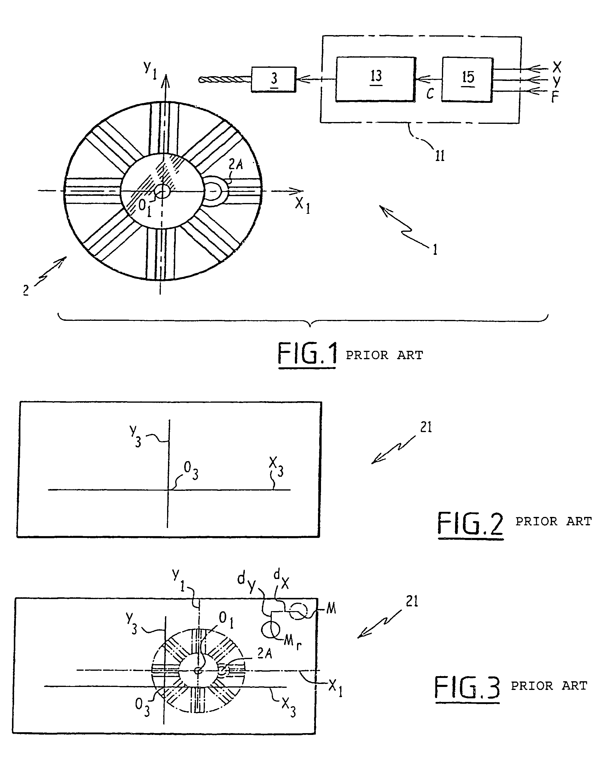
[0030]In the calibration method according to the invention, a template is drilled by the uncalibrated machine 1, shown in FIG. 1, as explained previously. In the illustrated example, this template 21 consists of an ophthalmic lens 21, as described with reference to FIG. 2, but could be another ophthalmic object such as a template of plastics or other material, provided with center and axis markings.

[0031]The adapter of the template 21 is removed, and the template is then cleaned to remove any trace of adhesive originating from the adapter from the surface of the template, and to leave the markings associated with the coordinate system O3, X3, Y3 visible on the surface of the template.

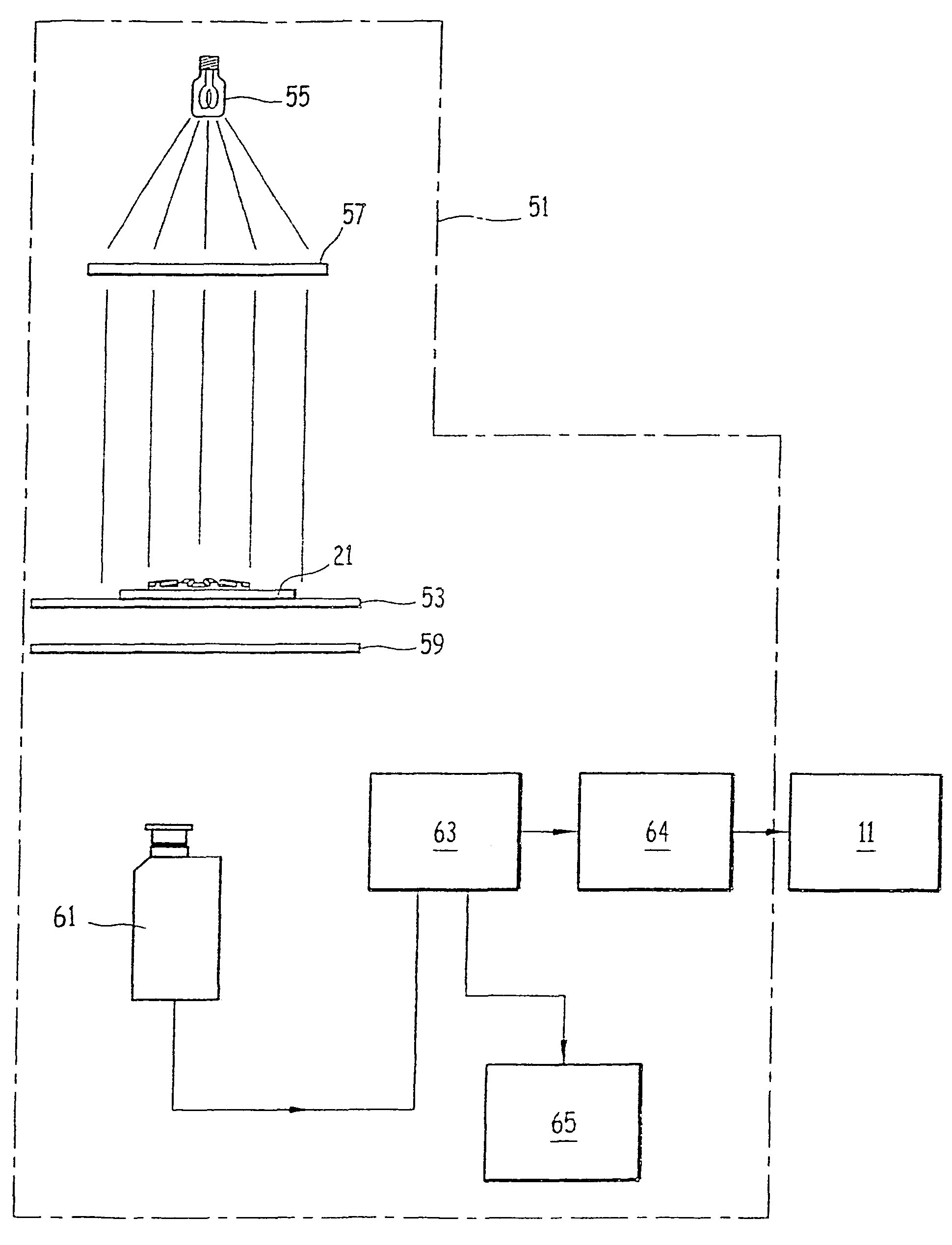
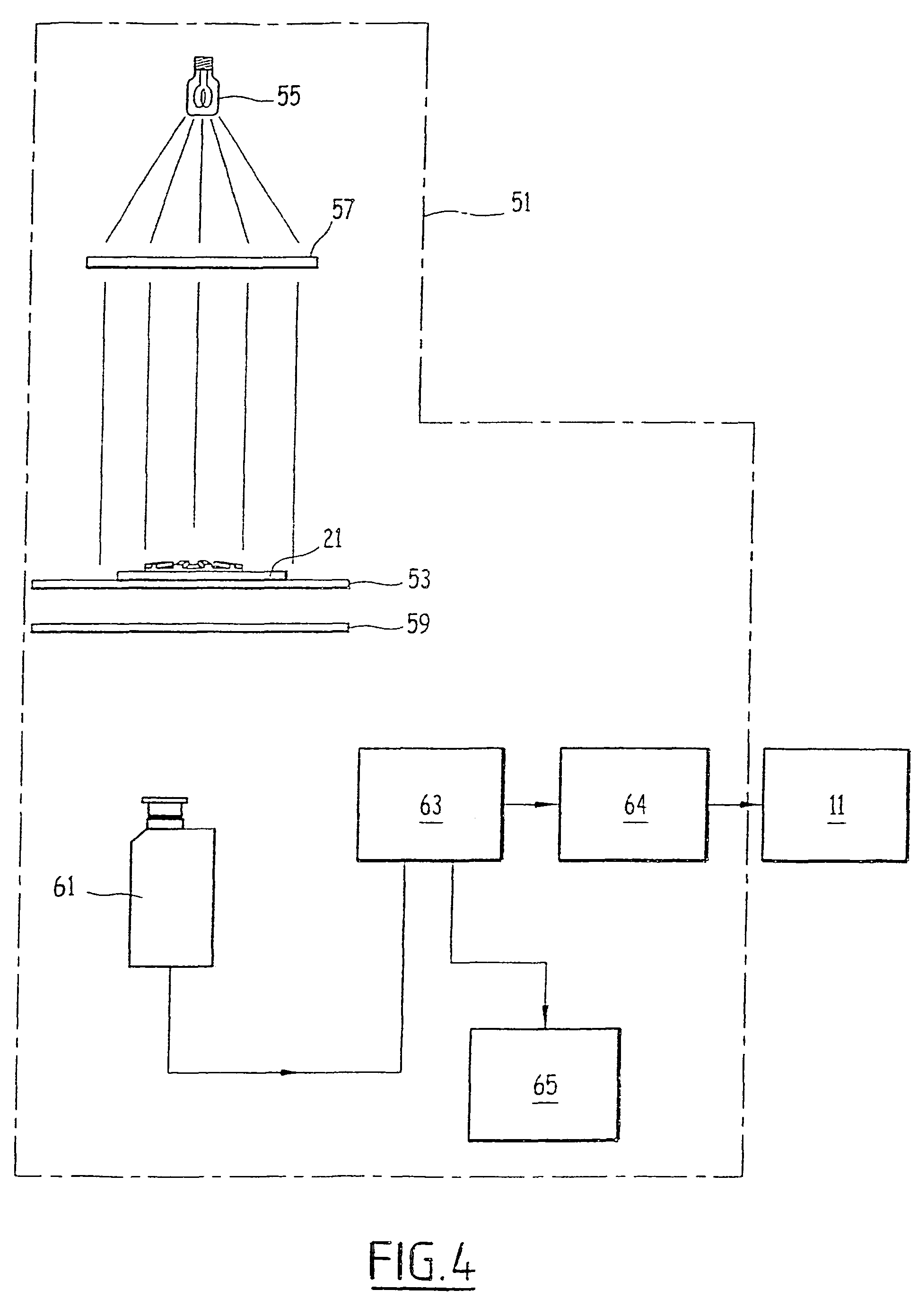
[0032]The coordinates dX, dY of the offset between the real drilling points Mr and theoretical drilling points M are then estimated by drilling calibration device 51 shown in FIG. 4.

[0033]This drilling calibration device 51 comprises a flat transparent support 53 on which can be placed the drilled templ...


PUM

PropertyMeasurementUnit
transparentaaaaaaaaaa
internal shapeaaaaaaaaaa
thicknessaaaaaaaaaa

Abstract

The invention relates to a method of calibrating an ophthalmic-lens-piercing machine, a device used to implement one such method and a ophthalmic-lens-machining apparatus comprising one such device. The inventive method applies to a machine including a piercing tool, a lens support which is associated with a first reference mark (O1, X1, Y1), and programmable tool-control means which are associated with a second reference mark expressing set co-ordinates which define a target piercing point (M). A template is placed on the support, and the template includes pre-applied markings defining a third reference mark (O3, X3, Y3), such that the third reference mark in essentially in line with the first reference mark. The template is pierced at a pre-determined point corresponding to a target point, and an image of the template this point position, and a correction is applied to the set co-ordinates that can compensate for the misalignment. A device is also provided which is used to implement the method, and to an ophthalmic-lens-machining apparatus including one such device.

Description

BACKGROUND OF THE INVENTION[0001]The present invention relates to a method for calibrating an ophthalmic lens drilling machine, the machine including a drilling tool; an ophthalmic lens support associated with a first coordinate system; and a programmable tool guidance means associated with a second coordinate system expressing command coordinates which define a target drilling point. In the method the following successive steps are carried out. A template is placed on the support, the template having pre-applied markings defining a third coordinate system related to the template, such that the third coordinate system is made to substantially coincide with the first coordinate system. The template is drilled in at least one predetermined point corresponding to a target point defined by predetermined command coordinates, such that a real drilling point is obtained.[0002]FIG. 1 shows schematically an ophthalmic lens drilling machine of a known type, which essentially comprises a suppo...

Claims


Application Information

Patent Timeline
Patent Type & Authority Patents(United States)
IPC IPC(8): G06F19/00B24B49/00B24B7/19G01D18/00G01D21/00G01B1/00G01C17/38G01M19/00G01P21/00G01M99/00G05B19/401
CPCG05B19/401G05B2219/45148G05B2219/45157G05B2219/50033
Inventor VASSARD, MICHAELVIDECOQ, JEAN-JACQUES
Owner LUNEAU TECH OPERATIONS
Why Eureka
Try Eureka