On-coil switched mode amplifier for parallel transmission in MRI

a technology of switching mode and parallel transmission, which is applied in the direction of magnetic measurements, instruments, measurement devices, etc., can solve the problems of system fidelity, synchronization, scaling, and fidelity of conventional parallel transmission techniques, and achieve the desired fidelity. the effect of fidelity

Active Publication Date: 2010-03-02
SIEMENS HEALTHCARE GMBH +2
View PDF3 Cites 21 Cited by
  • Summary
  • Abstract
  • Description
  • Claims
  • Application Information

AI Technical Summary

Problems solved by technology

However, conventional parallel transmission techniques have encountered issues with scaling, fidelity, and synchronization.
These systems tended not to scale well due to cabling duplication, power transmitter duplication, control duplication, and other issues.
Even when a small number (e.g., 4) of transmitters were employed, these systems may not have produced desired fidelity.
For example, conventional systems may have had complicated power distribution management and may have been difficult to synchronize.
Additionally, conventional systems typically had poor isolation between coils, resulting in degraded performance.
Furthermore, these systems may have required each element in an array to be tuned and matched, which is a very time-consuming procedure.
Conventional systems may also have been limited by their use of relatively low power (e.g., <50 W), low efficiency class A or class AB amplifiers.
While some systems may have included on-coil series and / or shunt-fed class-D amplifiers, even these conventional systems have suffered from several limitations including inadequate detuning and low efficiency.
Proposed systems that indicate that they may achieve higher efficiency still appear to lack adequate control mechanisms.
Due, at least in part, to these limitations, conventional systems may not have produced desired levels of amplitude and / or phase control and thus may have had less than desirable fidelity.

Method used


Image

  • On-coil switched mode amplifier for parallel transmission in MRI
  • On-coil switched mode amplifier for parallel transmission in MRI
  • On-coil switched mode amplifier for parallel transmission in MRI

Examples


Embodiment Construction

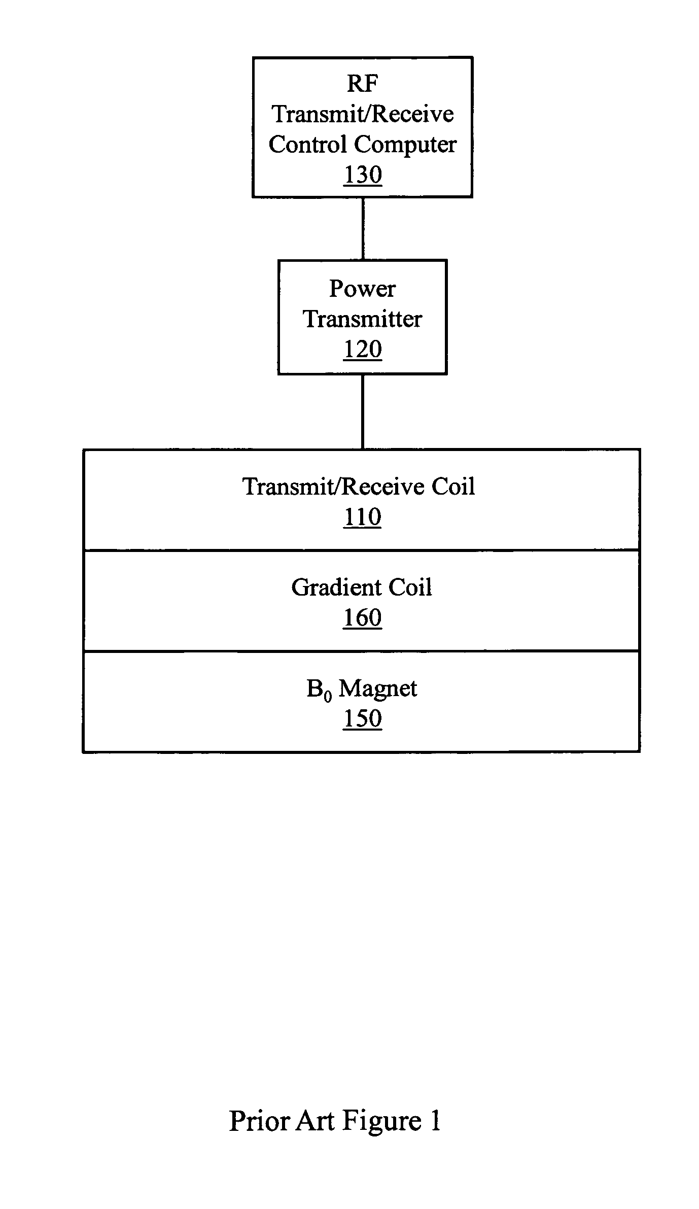
[0020]Prior Art FIG. 1 illustrates a conventional system that used a single transmit coil and a single receive coil. This conventional system could not perform parallel acquisition or transmission. This system presented the transmit coil 110 with an analog signal and the transmit coil 110 produced an analog output signal. The transmit coil 110 was powered by a single power transmitter 120 that may have been controlled by a computer 130. The system would also have included other standard MRI apparatus components (e.g., main field magnet 150, gradient coils 160, etc.) Thus, prior art FIG. 1 represents a class of devices characterized by a single power transmitter coupled to a single transmit receive coil that produced an analog signal and received an analog signal. The receiving was not in parallel.

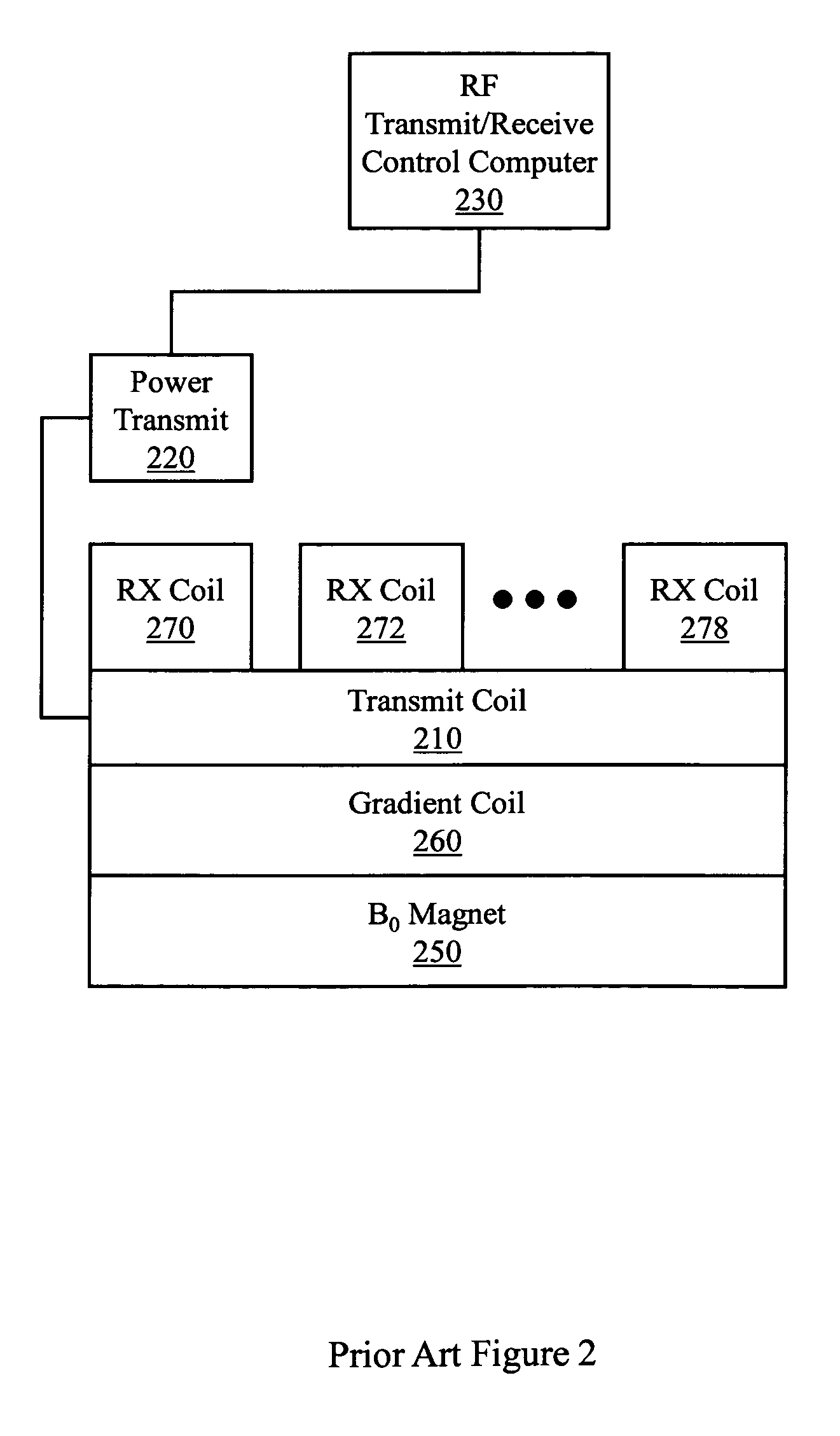
[0021]Prior Art FIG. 2 illustrates a conventional system that used a single transmit coil 210 and multiple receive coils (e.g., 270, 272 . . . 278). This conventional system could perform p...


PUM


Abstract

Example systems, apparatus, circuits, and so on described herein concern parallel transmission in MRI. One example apparatus includes at least two field effect transistors (FETs) that are connected by a coil that includes an LC (inductance-capacitance) leg. The apparatus includes a controller that inputs a digital signal to the FETs to control the production of an output analog radio frequency (RF) signal. The LC leg is to selectively alter the output analog RF signal and the analog RF signal is used in parallel magnetic resonance imaging (MRI) transmission.

Description

PRIORITY CLAIM[0001]This application claims the benefit of U.S. Provisional Patent Application 60 / 919,449, titled “On-Coil Switched Mode Amplifier For Parallel Transmission in MRI”, filed Mar. 22, 2007, and claims the benefit of U.S. Provisional Patent Application 60 / 905,941, titled “On-Coil Switched Mode Amplifier For Parallel Transmission in MRI”, filed Mar. 9, 2007.COPYRIGHT NOTICE[0002]A portion of the disclosure of this patent document contains material subject to copyright protection. The copyright owner has no objection to the facsimile reproduction of the patent document or the patent disclosure as it appears in the Patent and Trademark Office patent file or records, but otherwise reserves all copyright rights whatsoever.BACKGROUND[0003]Magnetic resonance imaging (MRI) involves the transmission of radio frequency (RF) energy. RF energy may be transmitted by a coil. Resulting magnetic resonance (MR) signals may also be received by a coil. In early MRI, RF energy may have been...

Claims


Application Information

Patent Timeline
Patent Type & Authority Patents(United States)
IPC IPC(8): G01V3/00
CPCG01R33/3415G01R33/36G01R33/3607G01R33/3614G01R33/5612
Inventor GRISWOLD, MARK A.HEILMAN, JEREMIAH A.RIFFE, MATTHEW J.HEID, OLIVERVESTER, MARKUS
Owner SIEMENS HEALTHCARE GMBH
Why Eureka
Try Eureka