Optical sensing methods and apparatus

a technology of optical sensing and optical meter, applied in the direction of instruments, speed/acceleration/shock measurement, measurement devices, etc., can solve the problems of large optical arrangement, high cost, and easy interference, and achieve the effect of simplifying the detection mechanism and simplifying the requirements of pulse tracking

Active Publication Date: 2010-03-02
HONG KONG APPLIED SCI & TECH RES INST
View PDF5 Cites 3 Cited by
  • Summary
  • Abstract
  • Description
  • Claims
  • Application Information

AI Technical Summary

Benefits of technology

[0008]By employing an optical reflection arrangement, a sensing arrangement could be more compact. Furthermore, by evaluating the variation in pulse width between a transmitted and a corresponding reflected pulse to give movement information, a simpler and speedier movement detection method is available.
[0010]In a convenient example, said train of optical pulses may comprise optical pulses of a pre-determined pulse width transmitted at pre-determined intervals. A pulse train of pre-determined pulse intervals will simplify detection mechanism.
[0011]In a convenient example, the pulse width of said train of pulses may be constant. A constant pulse width simplifies pulse tracking requirements.
[0014]To alleviate adverse interference from background optical pollution, such as interferences from fluorescent lamps, each said optical pulse may be modulated with a carrier frequency.

Problems solved by technology

However, such an optical arrangement is known to be bulky and requires expensive components.
Further, the reliability of conventional optical sensing arrangements is vulnerable to interference by ambient light noise such as interference from fluorescent lamp and background light.

Method used


Image

  • Optical sensing methods and apparatus
  • Optical sensing methods and apparatus
  • Optical sensing methods and apparatus

Examples


Embodiment Construction

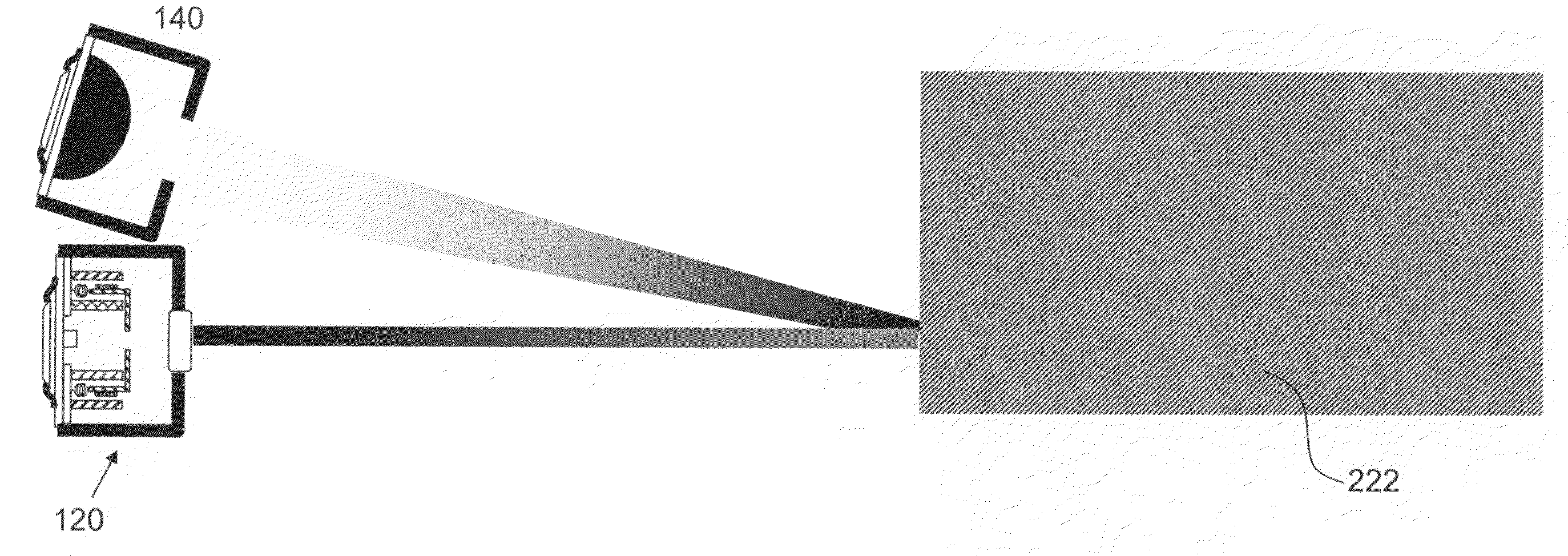
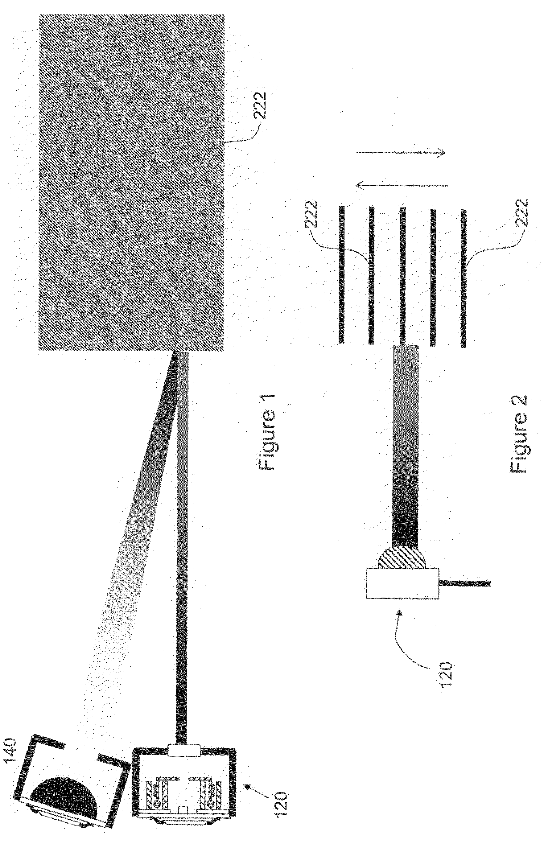
[0050]An embodiment of an optical sensing apparatus 100 of the present invention as depicted in FIGS. 1 to 5 comprises an optical source 120 and optical detector 140. The optical source 120 is arranged for projecting an optical beam towards a destination, and the optical detector is arranged and disposed for detecting optical signals returned from an object placed at the destination. By processing the optical signal detected at the optical detector due to reflection by an object at the destination, spatial characteristics, such as, for example, location, movement, proximity etc., could be evaluated with reference to the characteristics of the reflected optical signals.

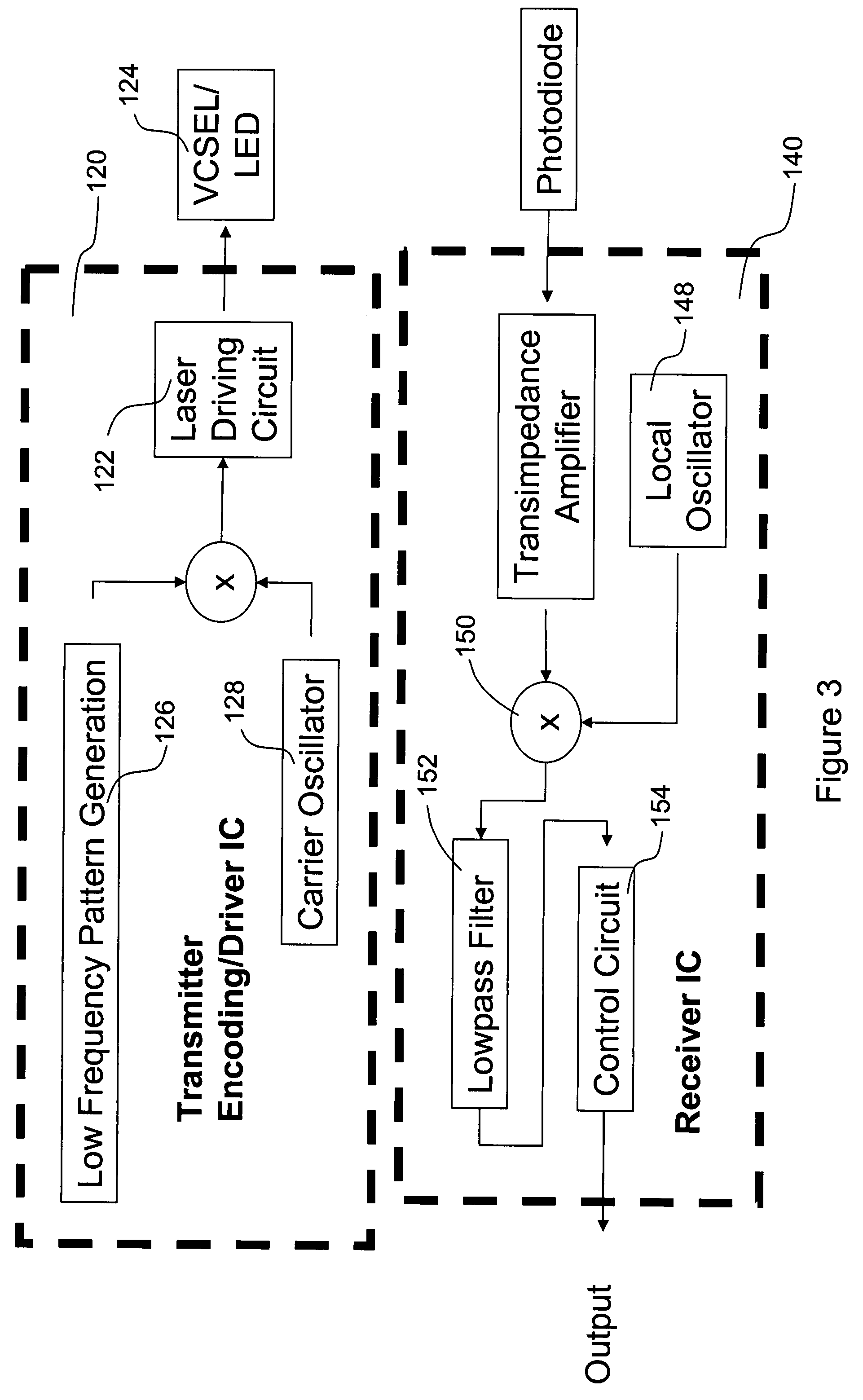
[0051]The optical source 120 comprises a light emitting source 124, such as an LED or a laser source, for example, a VCSEL laser source. The light source is driven by a driving circuit 122, such as a laser driving circuit which establishes the operation conditions of the light emitting source. In addition, a signal sou...


PUM


Abstract

A method of sensing movement or proximity of objects by optical reflection is provided. The method includes the steps of transmitting a train of optical pulses towards a destination, sensing optical pulses reflected from the destination, and sensing and evaluating movement or proximity characteristics of objects at the destination with reference to variation in pulse width between transmitted and reflected optical pulses.

Description

FIELD OF THE INVENTION[0001]The present invention relates to optical sensing apparatus and methods. More particularly, this invention relates to methods and apparatus for sensing movement of objects.BACKGROUND OF THE INVENTION[0002]Optical sensing techniques are widely used in automation and other applications. For example, optical sensors are used for detection of movement, presence and absence, and position, of objects in industrial automation process. An example of optical sensors known for such applications is the PX series photo-sensors by Keyence Corporation of the USA.[0003]In a typical optical sensing arrangement, an optical source is arranged on one side of an object for projecting an optical beam towards a destination. An optical detector is positioned on the other side of the object to monitor the detection or reception of optical signals originated from the optical source which are not blocked or intercepted by the objects. Spatial information of the objects, e.g., infor...

Claims


Application Information

Patent Timeline
Patent Type & Authority Patents(United States)
IPC IPC(8): G01P3/36
CPCG01S17/026G01S17/50G01S17/04
Inventor CHENG, KWOK SINGNG, HO SHANCHAU, LAI MANCHOW, YEUNG MINGTAO, TAO
Owner HONG KONG APPLIED SCI & TECH RES INST
Why Eureka
Try Eureka