Watercraft comprising a free-flying kite-type wind-attacked element as a wind-powered drive unit

a technology of wind-powered drive unit and free-flying kite, which is applied in the field of watercraft, can solve the problems of element on which wind acts are cut off, or it is not possible to carry out the direction chang

Active Publication Date: 2010-03-02
SKYSAILS GMBH & CO KG
View PDF20 Cites 27 Cited by
  • Summary
  • Abstract
  • Description
  • Claims
  • Application Information

AI Technical Summary

Benefits of technology

[0007]It is also advantageous for the operating elements and the means for force production to be provided in the immediate vicinity of the element on which wind acts, or even within it, and the corresponding control devices can also be provided at least partially directly at the element on which wind acts or even in it, so that it is also possible to largely dispense with complex signal transmission paths, which are susceptible to disturbances.
[0012]In order to match the forces to be applied for aerodynamic adjustments, it may be advantageous for at least one control line to have at least one bend or feedback area in the form of a pulley block, in which case the pulley block can be used both to step-up the ratio or to reduce it.
[0013]If the control lines form a matrix-like arrangement, this makes it easier to influence a kite in the manner of a paraglider. In this case, this arrangement relates to an area underneath the kite, from which the aerodynamic operations can be carried out jointly. In this case, it is advantageous for different control lines each to be driven in a combined form via a jointly driven operating element, since this reduces the number of drive elements. The jointly driven operating element may in this case, by way of example, comprise an element that is mounted such that it can rotate, a rocker, a lever, a toothed-belt pulley disk or the like, which is moved jointly via a drive motor. The individual control lines then lead to differently selected attachment points on the common operating element, so that respective linear movement results from the geometry of the attachment point, with the relevant control line being moved by this linear movement. In this case, the individual control lines may also be stepped up or reduced by means of pulley blocks or the like. This then results in the movement of the operating element being converted to the desired geometry change of the overall element on which wind acts, or on parts of it.
[0019]The actual position of the element on which wind acts in relation to the vessel can advantageously also be determined using altimeters and / or earth's magnetic field sensors on the element on which wind acts and the vessel, and / or with the aid of the alignment and the length of the hawser. This makes it possible to ensure that the data is still available even in the event of a system failure.
[0020]If a different sensor element is provided, which indicates imminent flow separation or flow separation that has already occurred, or is in the form of an element provided in the area of that surface of the element on which wind acts around which the flow passes and which emits an output signal when the airflow is attached to it, the flight control can be designed such that this prevents the element on which wind acts from dropping in the event of stalling.
[0022]If additional storage means and comparator means are provided which allow storage of signals associated with previous times together with signals which appear at later times, in such a manner that successive maneuver states can be compared, it is possible to provide predictive control of the element on which wind acts in the sense that the predictable consequences for vessel operation are taken into account on initiation of a maneuver.

Problems solved by technology

If, for example, lines were to become crossed over or entangled in this case, then it would either not be possible to carry out the direction change, or the element on which wind acts would have to be cut off.

Method used


Image

  • Watercraft comprising a free-flying kite-type wind-attacked element as a wind-powered drive unit
  • Watercraft comprising a free-flying kite-type wind-attacked element as a wind-powered drive unit
  • Watercraft comprising a free-flying kite-type wind-attacked element as a wind-powered drive unit

Examples


Embodiment Construction

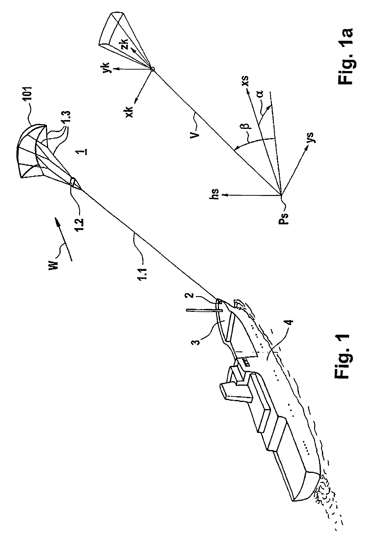
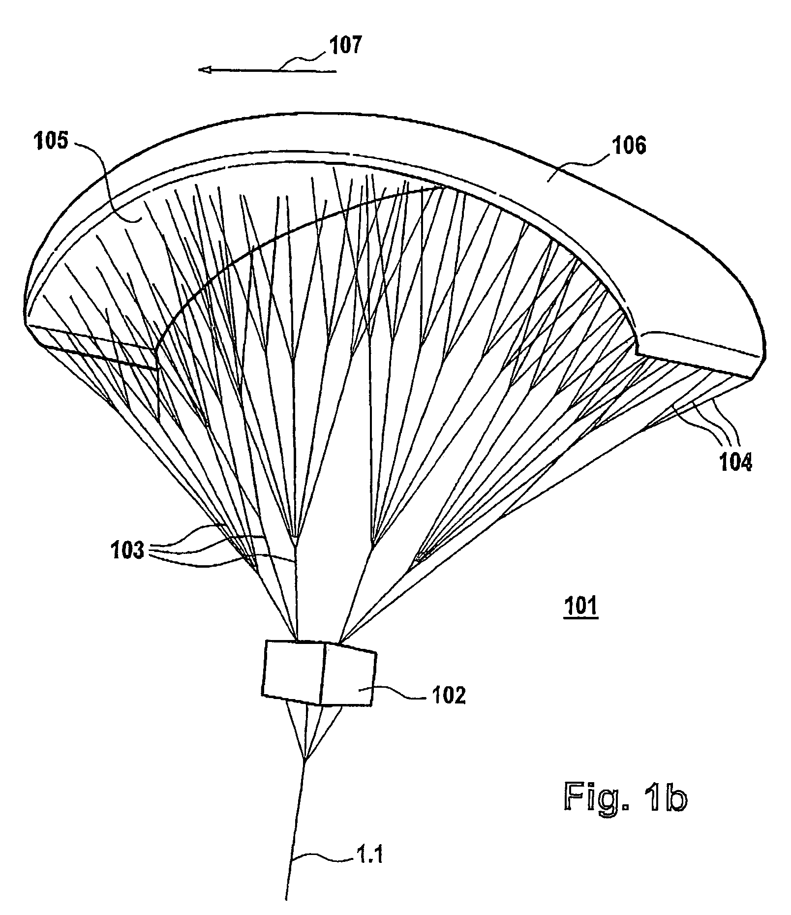
[0038]FIG. 1 shows an oblique plan view of a vessel which is being towed by the kite system. In this case, an element 1 on which wind acts is connected to a vessel 4 via a hawser 1.1 with an apparatus 2 on which force acts and which is provided in the bow area of the vessel 4. The hawser 1.1 is passed to a central gondola 1.2, from which a number of holding lines 1.3 originate, which are passed to the element 1 on which wind acts and is in the form of a paraglider with a kite profile, giving it the necessary shape. The details relating to this will be explained further below in the description. The apparent wind direction in the area of the element 1 on which wind acts is annotated W. The corresponding wind vector is indicated by its magnitude and direction. If required, its rate of change is also indicated by a variable B, which denotes the gusting, forms the mean time discrepancy between the wind speed and its mean value and can be represented as a scalar, which effectively forms ...


PUM


Abstract

Disclosed is a wind-powered watercraft in which a free-flying kite-type wind-attacked element that is provided with a profiled wing and is used as the exclusive, an auxiliary, or an emergency drive unit is connected to the vessel only via one traction rope, said traction rope optionally fanning out into a number of holding ropes. The wind-attacked element can be modified via at least one active drive element that is disposed thereupon and is effectively connected thereto by modifying the aerodynamic effect thereof in order to be guided into a given position relative to the watercraft or to dynamically maneuver.

Description

BACKGROUND OF THE INVENTION[0001]The invention relates to a watercraft which is propelled by the wind, in which a freely flying kite-like element on which wind acts and with a wing profile is connected to the vessel body only via a hawser.[0002]A watercraft such as this is known from WO / 097448. This vessel has the disadvantage that the aerodynamic shape of the element on which wind acts can be varied exclusively by means of additional control lines, which are routed to the hull of the vessel. This results in the difficulty that, when the element on which wind acts is flying at high altitudes, the additional lines represent a considerable mass because of the long length that they have to have, so that the propulsion performance is decreased, because this mass must additionally be supported by the wind propulsion element, and the corresponding force therefore cannot be converted to forward propulsion. Furthermore, a plurality of pulling lines can become entangled (fouled or twisted).S...

Claims


Application Information

Patent Timeline
Patent Type & Authority Patents(United States)
IPC IPC(8): B63H9/04G06F19/00B63H9/06
CPCB63H9/0685B63H2009/0692B63H9/072B63H9/071Y02T70/5236B63B79/10B63B2035/009
Inventor WRAGE, STEPHANMULLER, STEFAN
Owner SKYSAILS GMBH & CO KG
Why Eureka
Try Eureka