Variable valve mechanism

a valve mechanism and variable technology, applied in mechanical equipment, engines, machines/engines, etc., can solve the problems of increasing the internal mass of the engine, reducing performance, and worsening fuel economy, so as to reduce the loss of pumping and improve fuel economy

Inactive Publication Date: 2010-03-09
OTICS CORP
View PDF3 Cites 6 Cited by
  • Summary
  • Abstract
  • Description
  • Claims
  • Application Information

AI Technical Summary

Benefits of technology

[0009]The object of the present invention is to provide a variable valve mechanism that makes an inertial mass during high-speed operation less than an inertial mass during low-speed operation using a simple structure.
[0014]Using a simple structure, the variable valve mechanism according to the present invention can make the inertial mass during high-speed operation lower than during low-speed operation. In addition, closing the valve later during low-speed operation can reduce pumping loss and improve fuel economy.

Problems solved by technology

However, because this variable valve mechanism rocks both of the rocker arms as a single unit during high-speed operation, the inertial mass becomes greater than during low-speed operation.
This results in increased friction when the valve is being driven, which diminishes performance and worsens fuel economy.
It also becomes necessary for the rocker arms and cam followers to have sufficient strength to bear high loads, which increases the cost.
Further, the two rocker arms are de-linked during high-speed operation, such that only the high-speed rocker arm is rocked through a larger range by the high-speed cam than during low-speed operation, thus changing the amount of valve lift.
A switching mechanism that is provided in the variable valve mechanism links the two rocker arms into a single unit and rocks them during low-speed operation, but the configuration is such that the high-speed cam does not have any effect on the rocking.
During high-speed operation, the switching mechanism uses a switching pin to cause the follower not to slide idly, such that the high-speed cam causes the high-speed rocker arm to rock.
However, the variable valve mechanism must be provided not only with the switching mechanism for the rocker arms, but also with a mechanism that controls the movement of the follower, which makes the structure more complex.

Method used


Image

  • Variable valve mechanism
  • Variable valve mechanism
  • Variable valve mechanism

Examples


example

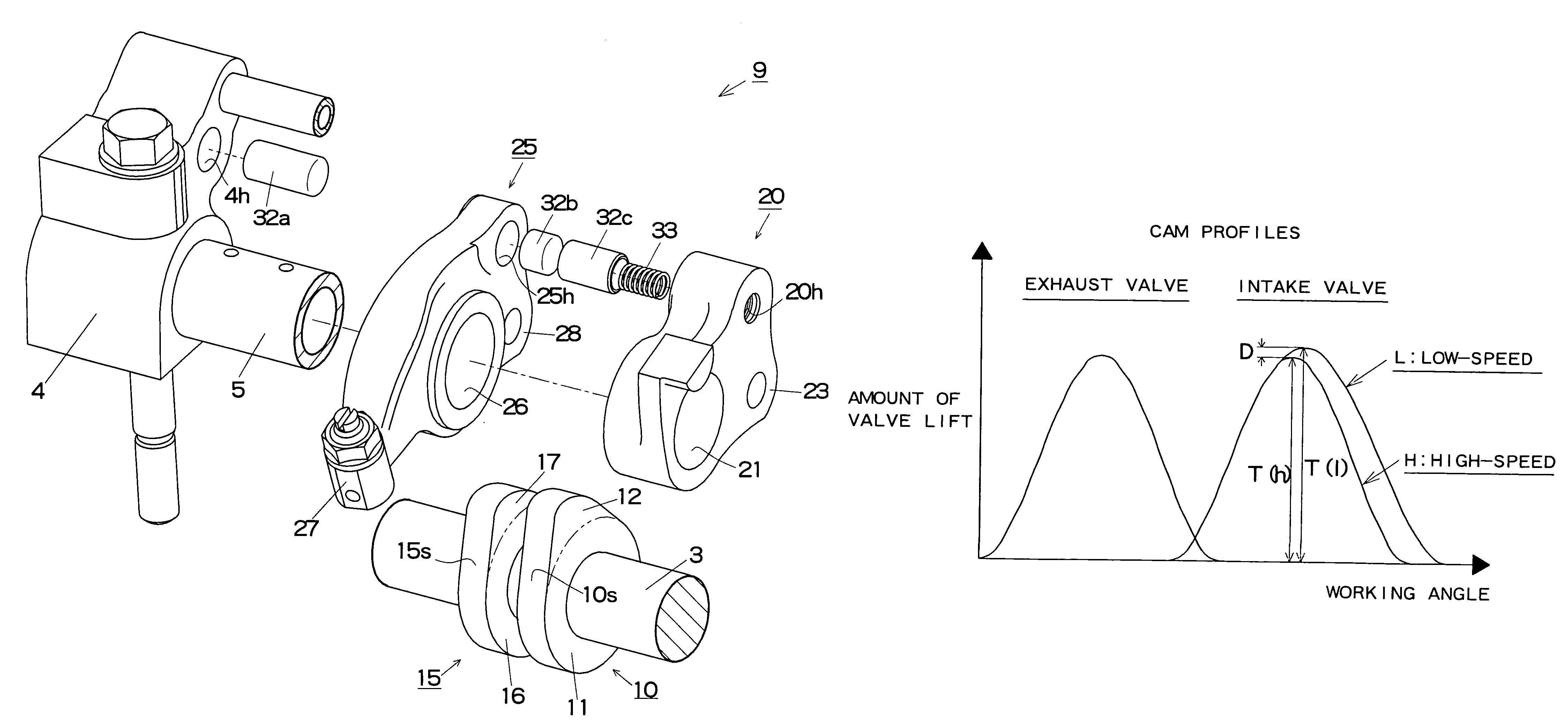
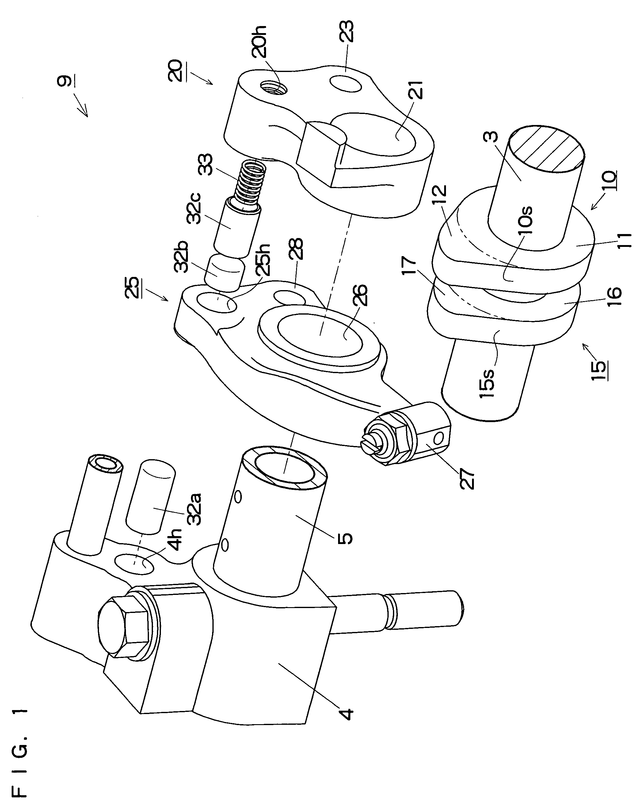
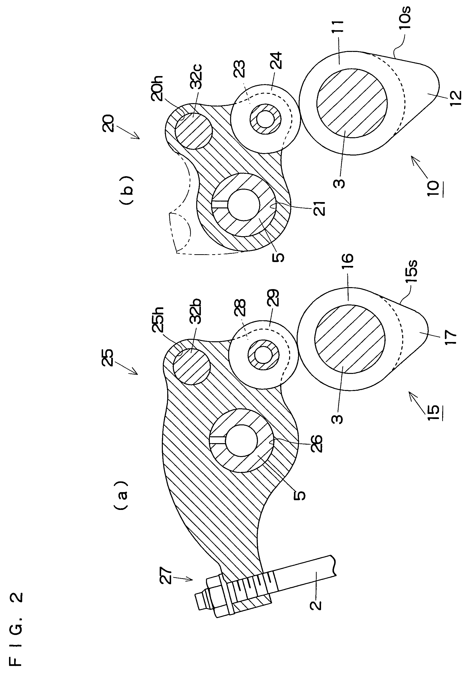
[0021]A variable valve mechanism 9 according to the present invention will be explained below, based on FIGS. 1 to 5, as a specific embodiment in an internal combustion engine that has two intake valves and two exhaust valves per cylinder. Note that the configuration is the same for both the intake valves and the exhaust valves, so only the configuration on the intake valve side will be illustrated and explained.

[0022]The variable valve mechanism 9 is configured such that it includes the low-speed cam 10, the high-speed cam 15, the low-speed rocker arm 20, the high-speed rocker arm 25, and a switching mechanism 30. The low-speed cam 10 and the high-speed cam 15 are arranged in parallel on a single camshaft 3. The low-speed rocker arm 20 and the high-speed rocker arm 25 are arranged in parallel on a rocker shaft 5 that is supported by a support 4, and are driven by the cams. The switching mechanism 30 switches the operation of the valve 2 by linking and de-linking the two rocker arms...


PUM


Abstract

A variable valve mechanism includes a low-speed cam, a high-speed cam, a low-speed rocker arm driven by the low-speed cam, a high-speed rocker arm driven by the high-speed cam, and a switching mechanism. A cam profile of the high-speed cam is set such that it does not exceed a cam profile of the low-speed cam. During low-speed operation, the switching mechanism links the low-speed and the high-speed rocker arms such that the low-speed cam causes the high-speed rocker arm to rock together with the low-speed rocker arm and to open and close a valve. During high-speed operation, the switching mechanism de-links the low-speed rocker arm and the high-speed rocker arm such that the low-speed cam causes the low-speed rocker arm to rock idly and the high-speed cam causes the high-speed rocker arm to rock independently and to open and close the valve. The cam profile of the low-speed cam is set such that the valve closes later than it does with the cam profile of the high-speed cam.

Description

INCORPORATION BY REFERENCE[0001]The present application claims priority under 35 U.S.C. §119 to Japanese Patent Application No. 2007-110439 filed on Apr. 19, 2007, which is incorporated herein by reference in its entirety.TECHNICAL FIELD[0002]The present invention relates to a variable valve mechanism that switches an amount of valve lift and valve opening and closing timings by linking and de-linking a plurality of rocker arms in an internal combustion engine.BACKGROUND OF THE INVENTION[0003]A type of variable valve mechanism is known that performs linking and de-linking between a low-speed rocker arm that depresses a valve and a high-speed rocker arm that does not directly depress a valve.[0004](a) For example, in a variable valve mechanism disclosed in Japanese Patent Application Publication No. JP-A-2005-23803, a nose of a high-speed cam is set higher than that of a low-speed cam, and during low-speed operation, the two rocker arms are de-linked, with only the low-speed rocker a...

Claims


Application Information

Patent Timeline
Patent Type & Authority Patents(United States)
IPC IPC(8): F01L1/34
CPCF01L13/0021Y10T74/2107
Inventor MASEGI, KIYOSHI
Owner OTICS CORP
Why Eureka
Try Eureka