Multiple article injection molding system

a technology of injection molding system and article, which is applied in the field of multi-article injection molding system, can solve the problems of affecting the front face affecting so as to facilitate the fabrication of the core and cavity block, and improve the quality of the mold block. the effect of quality

Inactive Publication Date: 2010-03-09
MACNEIL IP
View PDF4 Cites 2 Cited by
  • Summary
  • Abstract
  • Description
  • Claims
  • Application Information

AI Technical Summary

Benefits of technology

[0011]The system according to the invention makes fabrication of the core and cavity blocks easier, as these do not have to have coolant lines in them; the core and cavity blocks instead rely on flat rear faces to achieve good thermal conductance to the members on which they are mounted. The carrier plate and hot runner assembly have the coolant lines instead. The subassembly which is removed from the press is therefore far lighter than prior art apparatus and can be more easily moved with far less manpower and force. The use of remotely actuated face clamps means that workers never have to touch the faces of the core and cavity blocks, thereby obviating a source of damage.
[0012]According to another aspect of the invention, each core block has mounted therein a hot runner assembly nozzle seating ring having a rearwardly facing beveled surface. This seating ring is designed to receive a mating beveled (such as frustoconical) tip of a hot runner nozzle cap, which extends forwardly from a flat front face of the hot runner assembly. Preferably, the hot runner nozzle cap further has a circumferential groove to permit contact with coolant, and a pair of sealing O-rings on either side of the groove to seal the coolant from the molten polymer. The nozzle cap protects and cools the nozzle. The seating ring provides a precise locating function as the hot runner assembly closes onto the core block.

Problems solved by technology

To service the nozzle(s) of the hot runner assembly, a worker has had to remove these bolts with a wrench, which is time consuming and which subjects the front face of the mold block (which in part defines the geometry of the molded article) to possible damage.
It is also conventional practice to furnish the mold block or blocks with cooling channels through which water is circulated, in order to cool the molded article and to shorten molding cycle times. But these cooling channels are expensive and time-consuming to fabricate and drive up the cost of manufacturing the mold blocks.

Method used


Image

  • Multiple article injection molding system
  • Multiple article injection molding system
  • Multiple article injection molding system

Examples


Embodiment Construction

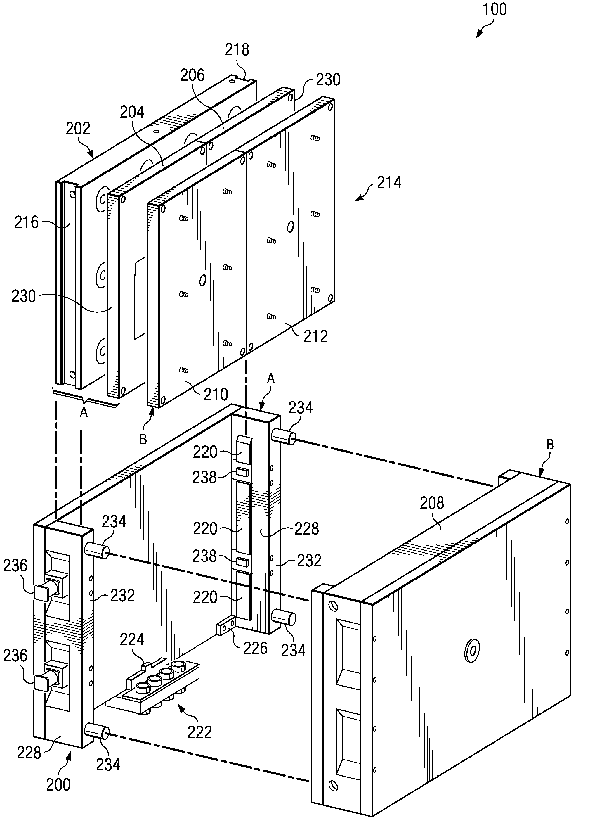
[0034]FIG. 1 shows an injection molding system 100 according to the invention, as it would appear assembled and in use. The system 100, as including its seven principal components (which will be described below), is compressed in a hydraulic press which has a stationary platen 102 and a movable platen 104. In one embodiment of the invention, a part line P divides the system 100 into an “A” half, which moves, and a “B” half, which when molding parts does not. The illustrated embodiment is designed to exert an injection molding pressure of at least 20,000 psi.

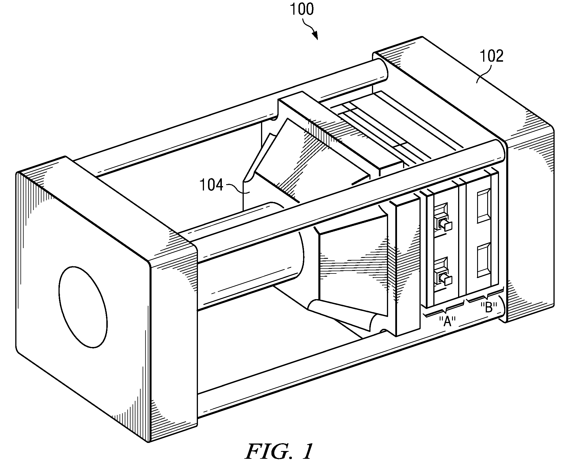
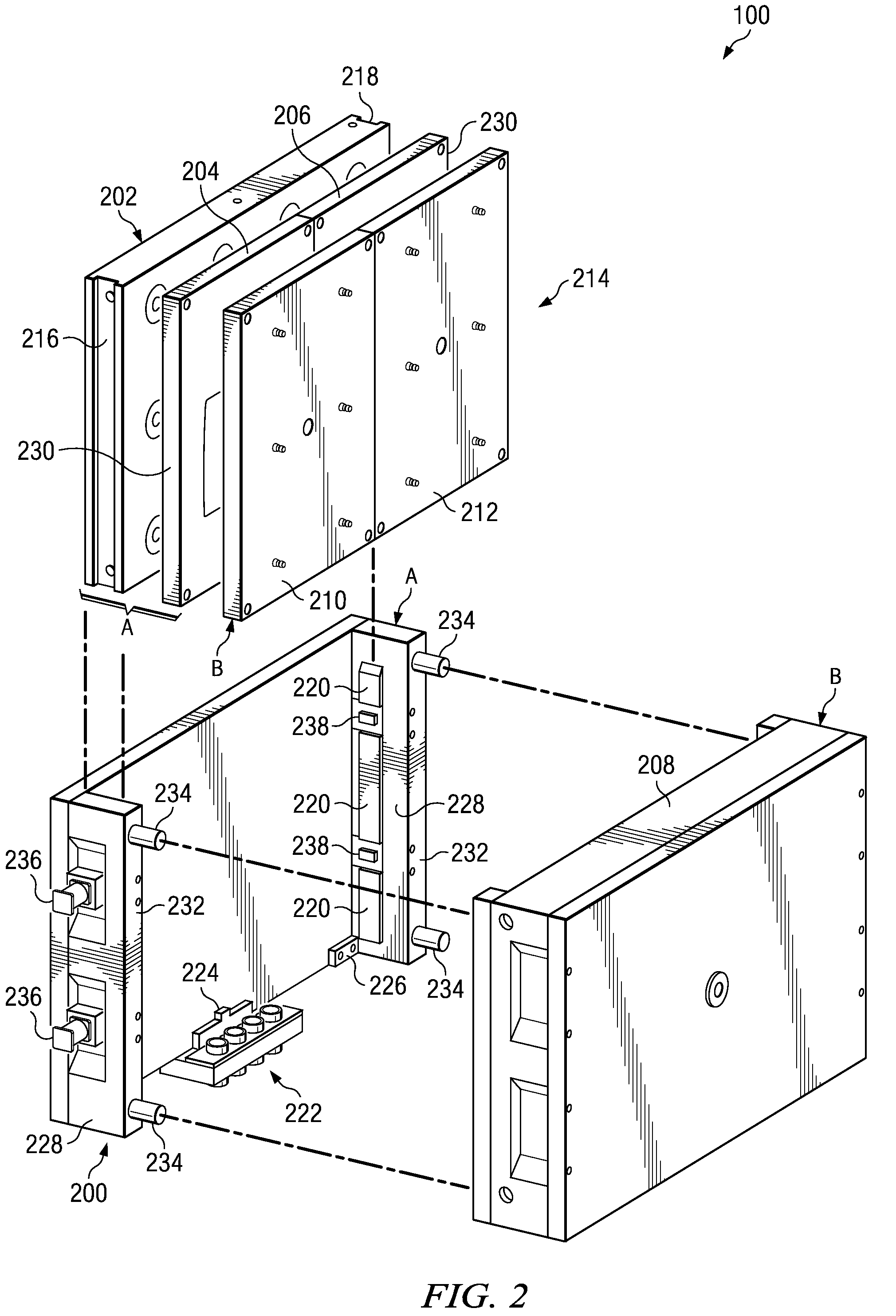
[0035]The major components of the system 100 are illustrated in exploded view in FIG. 2. In this embodiment, the “A” side includes a U-frame 200, a carrier plate 202 and two cavity mold blocks 204 and 206. The “B” side includes a hot runner assembly 208 and core mold blocks 210 and 212. In other embodiments the “A” side could remain stationary while the “B” side moves or both the “A” and “B” sides could move toward and apart from...


PUM

PropertyMeasurementUnit
pressuresaaaaaaaaaa
weightaaaaaaaaaa
pressureaaaaaaaaaa

Abstract

Principal components of injection molding apparatus include a U-frame, a carrier plate remotely affixable to the U-frame, preferably two cavity blocks remotely affixable to the carrier plate, a corresponding pair of core blocks, and a hot runner assembly remotely affixable to rear faces of the core blocks. These components are placed in a hydraulic press. In a molding operation, the U-frame, carrier plate and cavity blocks move as a unit relative to the hot runner assembly and the core blocks affixed thereto. To quickly change out one or both block pairs, a subassembly comprising the carrier plate and all core and cavity blocks is remotely released from the U-frame and the hot runner assembly and is removed as a unit. Face clamps in the front face of the carrier plate, the rear face of the cavity blocks, the rear face of the core blocks and the front face of the cavity blocks speed the changeout process and obviate potential damage to the molding geometry. A hot runner nozzle cap seat in each core block has a rear-facing bevel which receives a beveled hot runner nozzle cap tip.

Description

BACKGROUND OF THE INVENTION[0001]Elastomeric vehicle floor mats and like articles can be made by injecting a molten polymer into a mold, allowing the polymer to cool and / or crosslink, and then removing the molded article from the mold. In many cases the mold has two parts, separated by a part line. Often a first of these parts is a “core” mold block, and the other is a “cavity” mold block. The molten polymer is introduced via an orifice or gate in one of these mold blocks.[0002]The injection of molten polymer commonly is performed at very high pressures, such as 20,000 psi. To achieve these pressures, the assembled mold is placed in a press between a stationary platen and a mobile platen. The mobile platen terminates a hydraulic ram.[0003]In a conventional mold, the molten polymer is introduced into a gate formed in the back face of the mold block. A conduit or sprue communicates the back face of the mold block to a front face thereof, where a portion of the front face defines a por...

Claims


Application Information

Patent Timeline
Patent Type & Authority Patents(United States)
IPC IPC(8): B29C35/00
CPCB29C45/2602B29C2045/2689
Inventor MASANEK, JR., FREDERICK W.
Owner MACNEIL IP
Why Eureka
Try Eureka