

Electronic ballast
a technology of electronic ballast and ballast, which is applied in the direction of electrical equipment, instruments, light sources, etc., can solve the problems of individual lamps illuminating at different brightnesses, damage to lamps, and problems that are also apparen
- Summary
- Abstract
- Description
- Claims
- Application Information
AI Technical Summary
Benefits of technology
Problems solved by technology
Method used
Image

Examples
Embodiment Construction
[0005]The invention is based on the object of providing an electronic ballast (EB) for operating a lamp arrangement, in which, in comparison with conventional solutions, uniformly bright illumination of all the lamps and protection against premature ignition and electric shock are made possible with as few production costs as possible.
[0006]This object is achieved according to the invention by the features of claim 1. Particularly advantageous embodiments of the invention are described in the dependent claims.
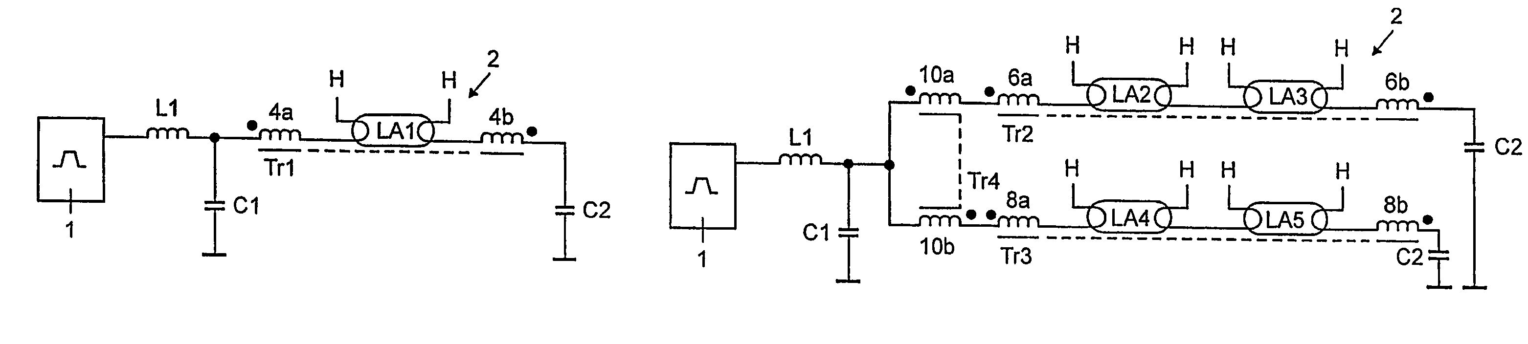
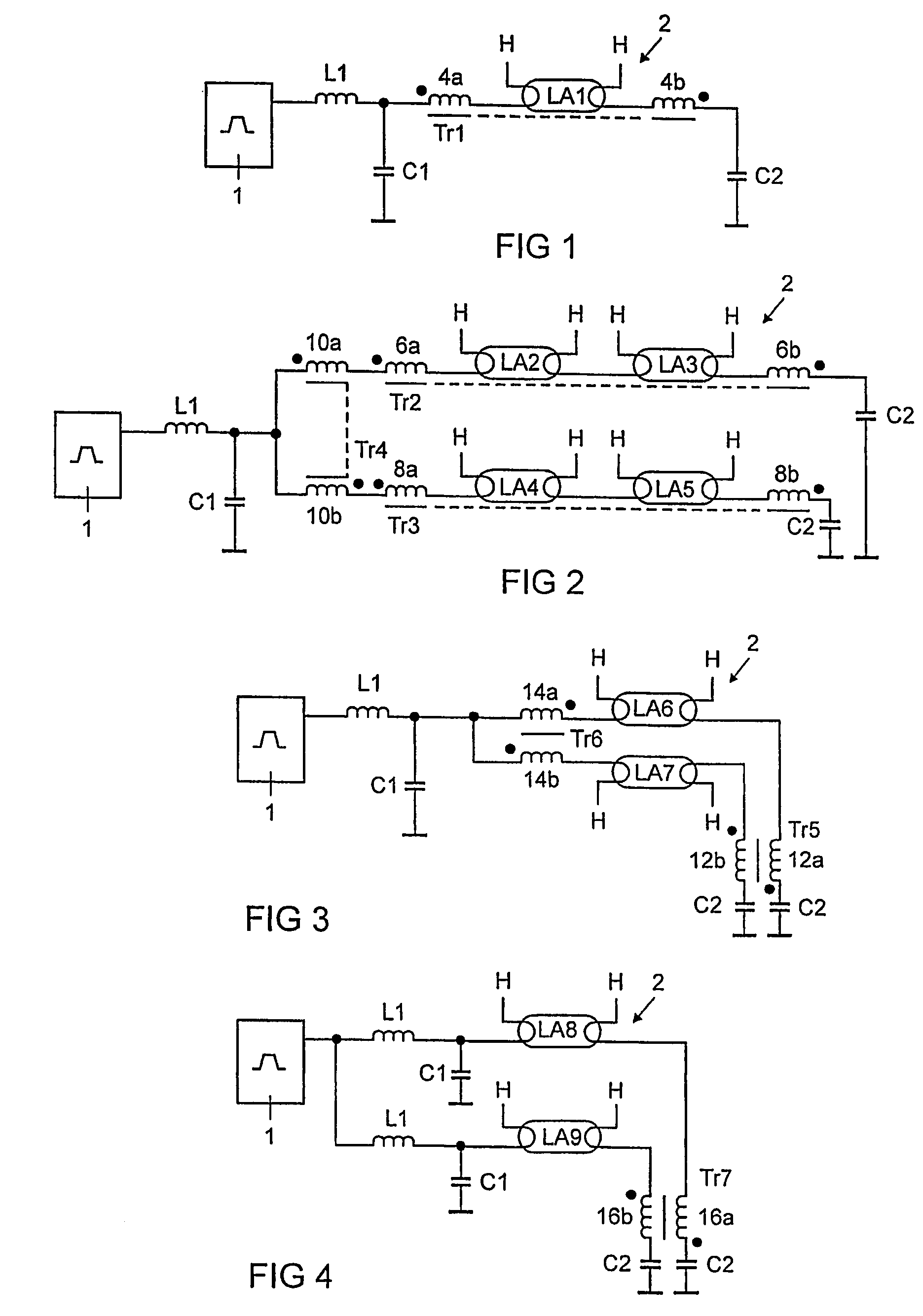
[0007]The electronic ballast (EB) according to the invention for operating a lamp arrangement having at least one lamp, in particular a low-pressure discharge lamp, has at least one transformer for balancing the lamp currents, the transformer having two windings, which are assigned to one or more lamps of the lamp arrangement. According to the invention, the transformer is in the form of a saturation balancing inductor. On the one hand, this inductor balances the lamp currents,...
PUM
 Abstract
Description
Claims
Application Information