Wall mountable frame structure for mounting equipment

a frame structure and equipment technology, applied in the direction of mechanical equipment, walls, machine supports, etc., can solve the problems of unsightly, difficult installation, and visible wiring and cabling for the operation of various devices, and achieve the effect of reducing the number of devices and reducing the cost of installation

Inactive Publication Date: 2010-03-16
VANTAGE POINT PRODS
View PDF43 Cites 21 Cited by
  • Summary
  • Abstract
  • Description
  • Claims
  • Application Information

AI Technical Summary

Benefits of technology

[0054]There has thus been illustrated and described a wall mountable frame structure for mounting various devices, including home entertainment equipment or other similar devices which provides a visually pleasing profile because the point of contact of the periphery of the device is not visual because of the profile shape that is hiding any gaps that may occur as a result of uneven wall structures. There is also provided a substantial space between the wall and frame to permit the passage of tubes, wires, or cables and the like connected to equipment and also permits the utilization of standard electrical wiring plugs. Clearance is provided between the cladding panels and frame (approximately ½ inch) to allow tubes, wires and cables to be easily passed therethrough. The frame structure is adjustably mounted on support brackets affixed to the wall and after the frame structure has been appropriately positioned as desired the frame structure is tightened to the support brackets to prevent movement of the frame structure thereafter. While various embodiments and structures of the present invention have been illustrated and described, it is to be recognized that the scope of the present invention is determined by the claims set forth below:

Problems solved by technology

Many such mounting systems are extremely complicated and difficult to install and often require an electrician or cabinet maker to accomplish this task.
Even when such is accomplished, a remaining problem is that the wiring and cabling necessary to operate the various devices remains visible and is unsightly.

Method used


Image

  • Wall mountable frame structure for mounting equipment
  • Wall mountable frame structure for mounting equipment
  • Wall mountable frame structure for mounting equipment

Examples


Embodiment Construction

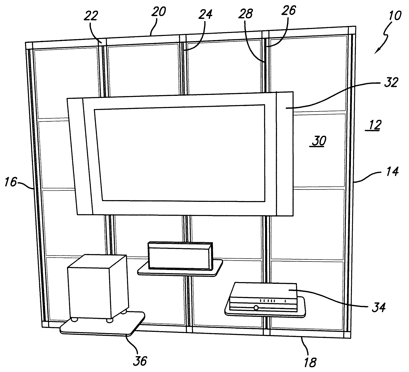
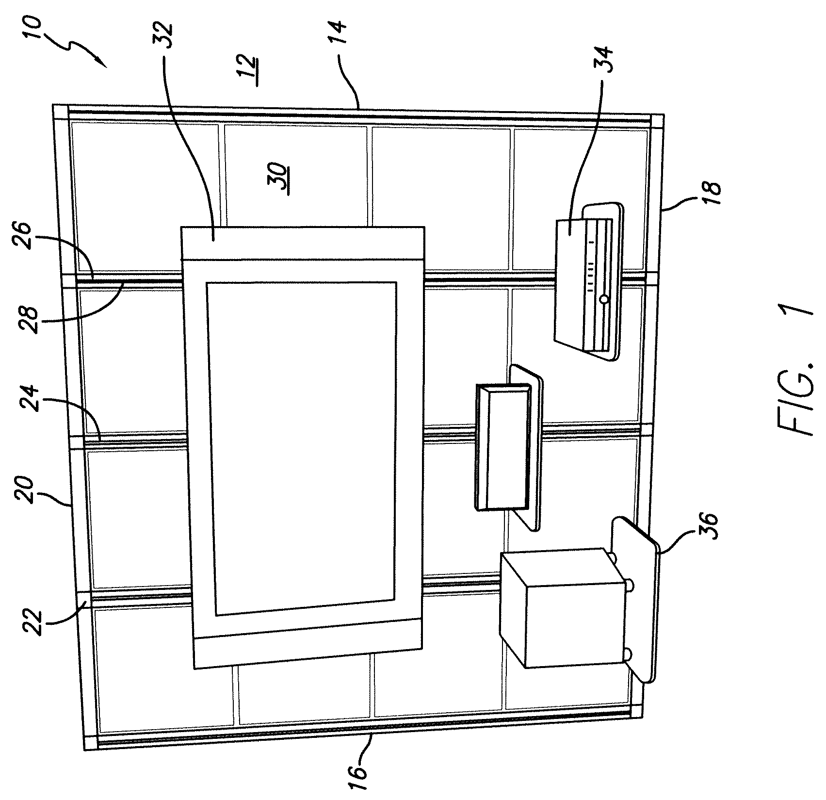
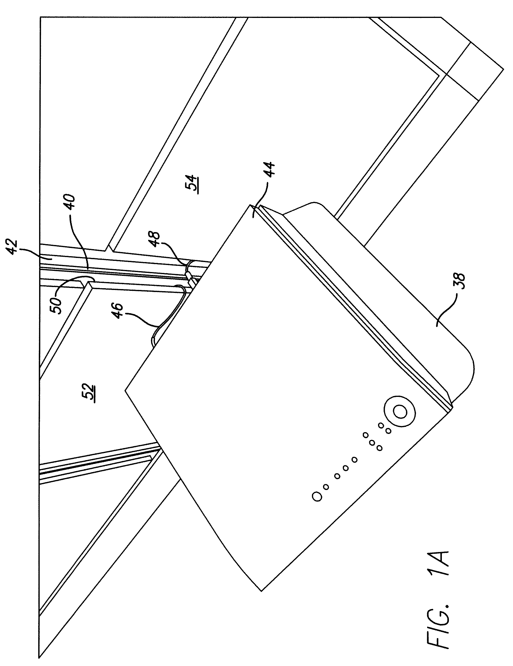
[0037]The present invention is a modular or non-modular wall mountable frame system which is adapted to be attached directly to a wall or to hang from mounting brackets or rails which are installed directly to the wall. The frame structure encompasses an area large enough to provide for numerous attachment points to the wall such that the load carried by the frame is distributed through these various attachment points. The frame has a plurality of attachment points on its exterior face where any assortment of equipment including entertainment equipment or similar devices may be attached through the utilization of any of a variety of mounting structures. The frame system is adapted to detachably receive a plurality of cladding panels which creates a hollow space between the cladding panels and the wall upon which the frame has been installed. The dead air space provides a sound barrier and prevents sound emanating from entertainment speakers from traveling into adjacent rooms. This p...


PUM


Abstract

A wall mountable frame structure for supporting appliances, entertainment equipment or other devices including peripheral horizontal and vertical structural beams with at least one intermediate vertical beam extending between and secured to the horizontal beams. A plurality of cladding panels removably attached to the vertical beams by way of a stud having a trapping member at its terminus which fits within a complimentary receiving portion of the vertical beams to secure the cladding panel to the vertical beams. A support bracket to be affixed to a wall and having mounting forks pivotally secured thereto is provided. A plurality of transverse mounting members are affixed to the vertical beams and are received by the mounting forks to secure the frame to a wall. The mounting forks are rotatable between first and second positions with the frame positioned away from the wall in the first position and against the wall in the second position. Each of the vertical beams defines a channel within which there is received a moveable fastener which is utilized to attach one or more pieces of equipment to the frame structure. The movable fastener frictionally engages the side walls of the channel to hold the fastener in position once it is adjusted to a desired location.

Description

RELATED APPLICATION[0001]This application is based on provisional application 60 / 810,541 filed Jun. 1, 2006, and benefit of the filing data thereof is hereby claimed.FIELD OF THE INVENTION[0002]The field of the invention is an apparatus for mounting equipment of many types in the office, industrial or home environments.BACKGROUND OF THE INVENTION[0003]The present invention relates to an apparatus for mounting appliances or equipment of many types in offices, industrial areas or homes and is particularly useful for mounting home entertainment devices such as a television set, speakers, CD / DVD players and the like and more particularly, to a frame structure which is adapted to be mounted upon a wall and to which such home entertainment devices may be affixed.[0004]It has become recognized in the industry, particularly as a result of the development of flat panel television sets that means to mount such devices to the wall of a structure have become extremely important. Many such mount...

Claims


Application Information

Patent Timeline
Patent Type & Authority Patents(United States)
IPC IPC(8): E04B2/74
CPCE04F13/081F16M13/02E04B2002/7483
Inventor BURNS, DON R.
Owner VANTAGE POINT PRODS
Why Eureka
Try Eureka