Curved blade mixing device

Inactive Publication Date: 2010-03-16
LURGI LENTJES AG
View PDF25 Cites 1 Cited by
  • Summary
  • Abstract
  • Description
  • Claims
  • Application Information

AI Technical Summary

Benefits of technology

[0003]Usually, mixing devices of this type are composed of at least two horizontally intermeshing screws, which are constructed with different lengths and diameters according to the needs. For obtaining certain properties, such as the increase of the transformation or reaction speed or the maximization of product yield and product quality, the mixing device is varied with respect to the solid retention time, the temperature in the reactor or the system pressure.
[0010]Based upon this state of the art, it is object of the invention to improve the former mixing device such that for a predetermined reactor length, the retention time is increased and the material to be processed is transported at essentially the same speed irrespective of the radial distance thereof from the rotational axis.
[0011]According to the invention, this aim is achieved for the initially mentioned mixing device in that at least two opposing rows of blades are mounted on each shaft and each row of blades consists of 2 to 20 individual blades and that the blades are fixed to the shaft at an incidence angle α with respect to the longitudinal axis of the shaft, wherein the blades are curved in themselves, such that the blades form the angle of incidence α at the fixing point on the shaft and the angle of incidence β on the outer diameter. By virtue of the fact that a row of individual blades is used instead of a continuous screw, a particularly efficient mixing is achieved. Thanks to a curvature of the blades, whereby a different angle of incidence with respect to the longitudinal axis of the shaft results with increasing diameter, the axial speed of the particles to be mixed can be evened out over the entire cross section of the reactor.
[0013]If the angle of incidence of the blades continuously decreases from the base point on the shaft DW towards the outer diameter DA, the axial speed of the particles to be mixed decreases on the outer diameter DA proportionally to the axial speed on the diameter DW of the shaft. On condition that the outer diameter DA is twice as long as the diameter DW(DA=2 DW), the same axial speed will be obtained over the entire cross section of the reactor, if the angle of incidence β on the outer diameter DA is half as great as the angle of incidence α on the diameter DW of the shaft. The shear effect during the transport of the solids through the mixing device is increased by a multiple interruption of the helix. The mixing intensity is increased and thereby the complete mixing is not only obtained at half the reactor length, but clearly earlier. With the same reactor length, a longer retention time for the chemical reaction is achieved, which enables new plants to have either shorter reactor lengths or alternatively longer reaction times and thus lower reaction temperatures.

Problems solved by technology

But this could not be achieved hitherto.
In order to increase the retention time, a longer reactor, which could solve the problem, would be an extremely expensive solution, since the shafts and screws are made of high temperature steel and have an outer diameter comprised between 0.8 and 3 m as well as a length comprised between 6 and 15 m.

Method used


Image

  • Curved blade mixing device
  • Curved blade mixing device
  • Curved blade mixing device

Examples


Embodiment Construction

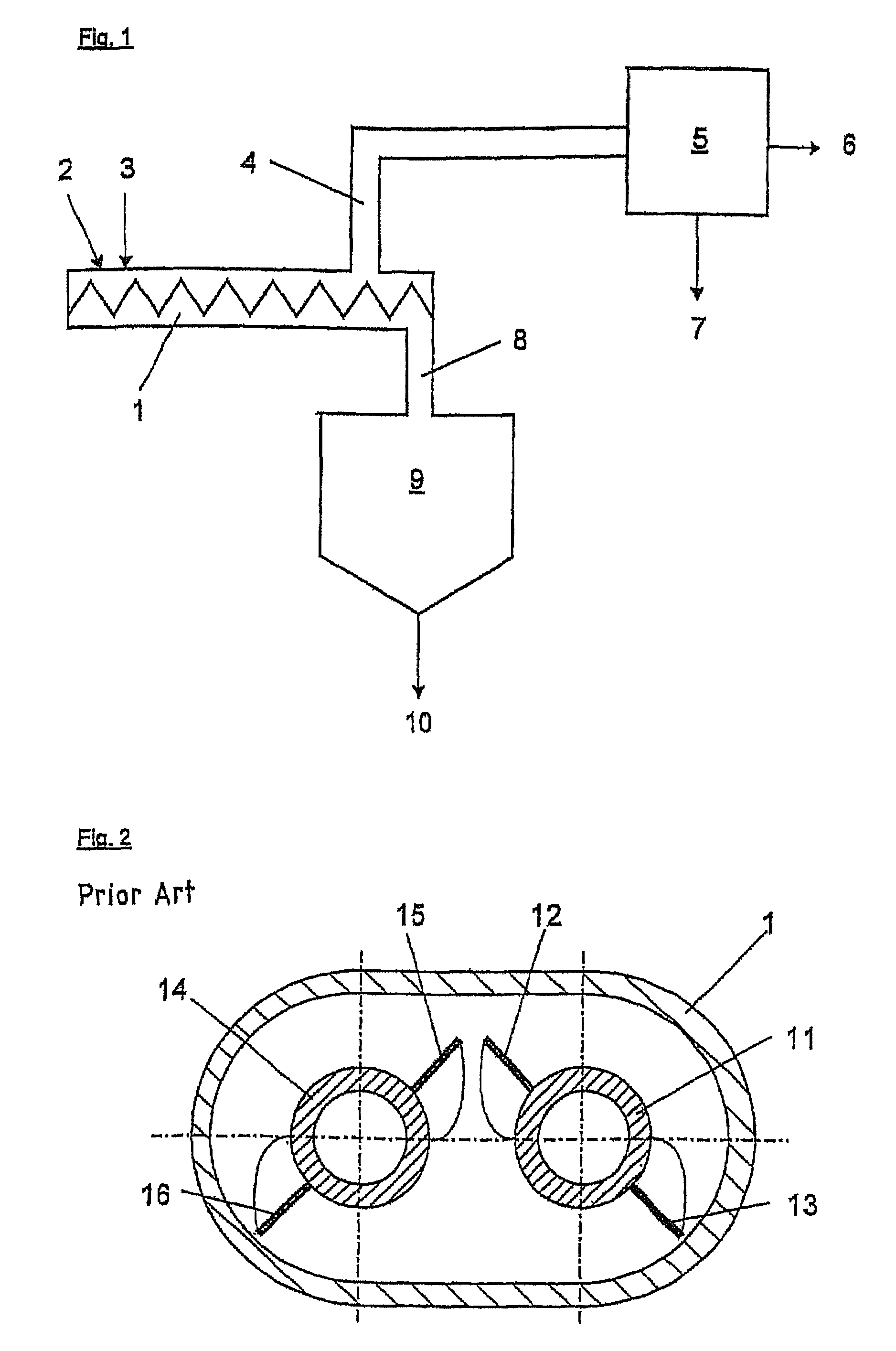
[0023]Hot heat transfer medium coke is for example introduced via pipe (2) into mixing device (1) of FIG. 1 and the residual oil to be processed is introduced via pipe (3). In the present case, mixing device (1) comprises at least two horizontal intermeshing screws, which thoroughly mix the introduced materials and transport them to outlet channel (8). Gases and vapours can leave the mixing device via drain channel (4) for condensation (5). From condensation (5), gases are evacuated via pipe (6) separately from product oil, which is evacuated via pipe (7). The coke bearing solid mixture, which has passed through mixing device (1) is guided via outlet channel (8) to a vessel (9). The dried coke can be evacuated from this vessel (9) via pipe (10) and be returned to the process. Instead of further processing residual oil with heat transfer medium coke, the mixing device can of course also be used for the regeneration of e.g. bitumen, plastics, coke, peat or biomass, whereby the entire ...


PUM

PropertyMeasurementUnit
Lengthaaaaaaaaaa
Lengthaaaaaaaaaa
Timeaaaaaaaaaa

Abstract

The aim of the invention is to improve an existing mixing device in such a manner that for a predetermined reactor length, retention time is increased and the material which is to be processed is transported at essentially the same speed irrespective of the radial distance thereof from the rotational axis. As a result, at least one row of blades is arranged on each shaft and each row of blades comprises at least two individual blades and the blades are fixed to the shaft at an incidence angle α in relation to the longitudinal axis of the shaft. The blades are curved in themselves, such that the blades form an angle of incidence α at the fixing point on the shaft and an angle of incidence β on the outer diameter DA. By virtue of the fact that a row of individual blades is used instead of a continuous screw, efficient mixing of charging material and coke can be achieved, the angle of incidence is reduced from the inside to the outside and the axial speed of the particles which are to be mixed is evened out on the total cross section of the reactor, thereby enabling a stop-type flow to be obtained.

Description

FIELD[0001]The invention relates to a mixing device as well as to an associated mixing method for the use as continuously working reactor.BACKGROUND AND SUMMARY[0002]These continuously working reactors are used for the regeneration of for example crude oil vacuum residues, refinery residues, bitumen or plastics by mixing them with a hot granular heat transfer medium and heating them up to the desired temperature.[0003]Usually, mixing devices of this type are composed of at least two horizontally intermeshing screws, which are constructed with different lengths and diameters according to the needs. For obtaining certain properties, such as the increase of the transformation or reaction speed or the maximization of product yield and product quality, the mixing device is varied with respect to the solid retention time, the temperature in the reactor or the system pressure.[0004]DE-A-19724074 and DE-A-19959587 describe a method for the regeneration of residual oil, in which hot coke as ...

Claims


Application Information

Patent Timeline
IPC IPC(8): B01F7/08B01F7/04
CPCB01F7/042B01F27/702
Inventor WEISS, HANS-JURGENZENTNER, UDONEUMANN, BURGHARDSCHMALFELD, JORG
Owner LURGI LENTJES AG
Why Eureka
Try Eureka