Gas-liquid separator for filtration operation

A technology of gas-liquid separator and gas-liquid separation device, which is applied in the direction of separation methods, dispersed particle separation, chemical instruments and methods, etc., and can solve problems such as improving the energy consumption of filtering ore feeding, increasing the height of filtering ore feeding, and increasing infrastructure investment. , to reduce energy consumption, increase retention time, and avoid cavitation

Pending Publication Date: 2018-11-30
中冶北方(大连)工程技术有限公司
View PDF0 Cites 0 Cited by
  • Summary
  • Abstract
  • Description
  • Claims
  • Application Information

AI Technical Summary

Problems solved by technology

At present, the gas-liquid separator generally uses a gravity drainage tank in the current mineral processing plant. This kind of equipment needs to set the gravity drainage tank and filter on a platform above 10 meters high to overcome the influence of atmospheric pressure on the discharge of the filtrate and prevent the filtrate from The air outlet of the gravity drainage tank enters the vacuum pump to pollute the working fluid of the vacuum pump and cause damage to the vacuum pump
Adopting the method of gravity drainage, the feeding of the entire filter and the filter are raised by more than 10 meters, which not only greatly improves the height of the plant and increases the investment in infrastructure, but also increases the height of the filtering feeding, greatly improving the filtering feeding required energy consumption
Moreover, gravity drainage is adopted. In order to prevent the filtrate from flowing back, a water-sealed box must be installed under the filtrate tank. When the filter cloth is damaged, fine-grained minerals enter the water-sealed box with the filtrate, which is easy to cause blockage, resulting in the final filtrate entering the vacuum pump with the air. , resulting in changes in the water quality of the vacuum pump working fluid and damage to the vacuum pump

Method used


Image

  • Gas-liquid separator for filtration operation
  • Gas-liquid separator for filtration operation
  • Gas-liquid separator for filtration operation

Examples


Embodiment Construction

[0022] The specific embodiments of the present invention will be further described below in conjunction with the drawings.

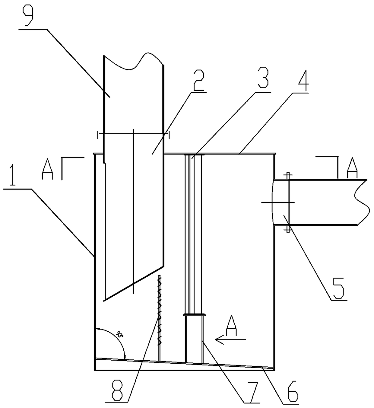
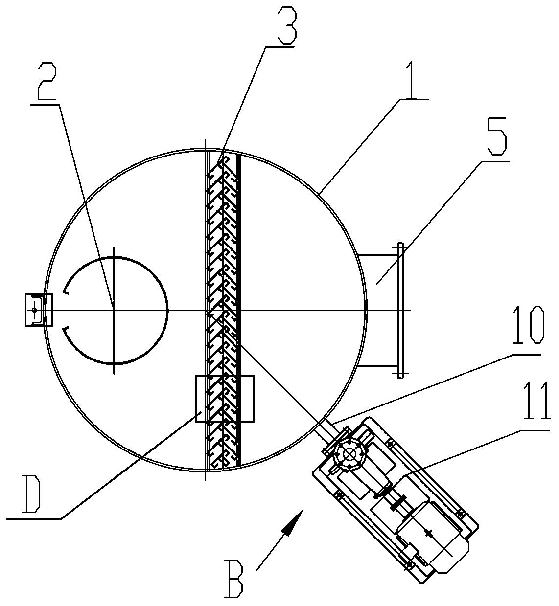
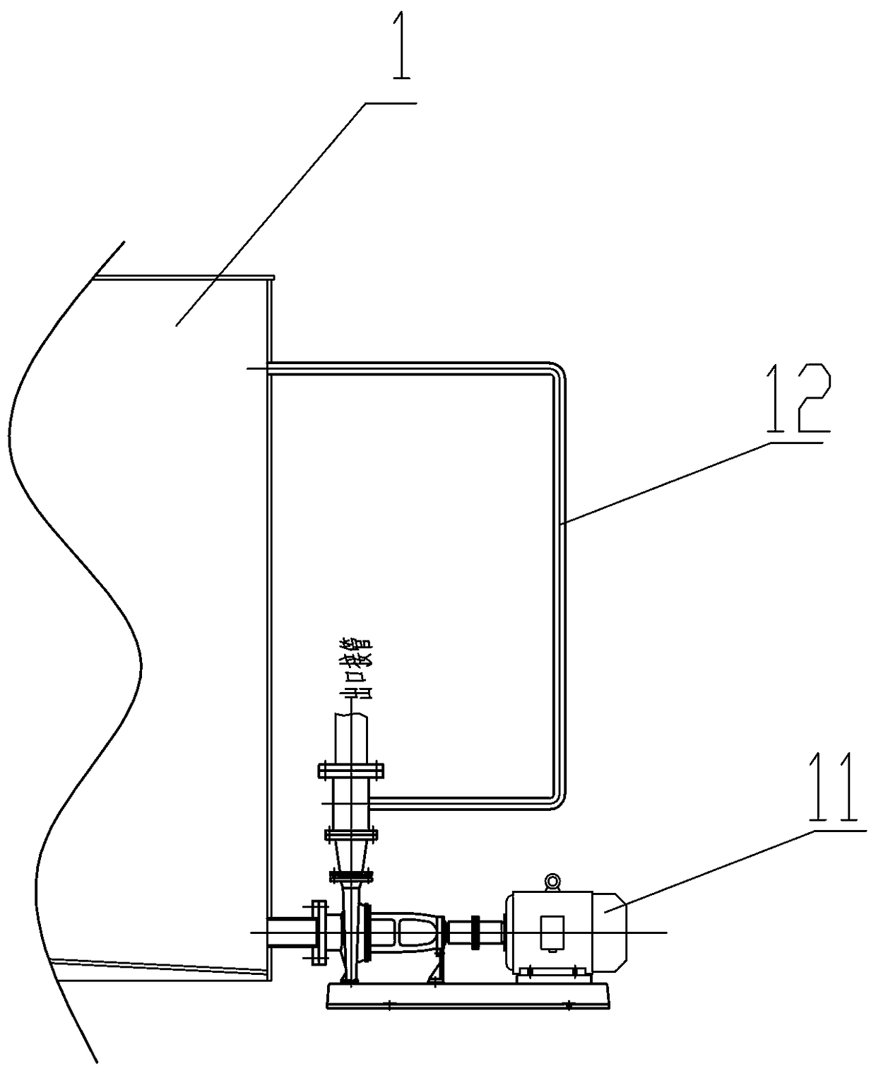
[0023] Such as Figure 1-Figure 4 As shown, a gas-liquid separator for filtration operation of the present invention is characterized in that:

[0024] The gas-liquid separator is composed of a tank body 1, a suction pipe 2, a gas-liquid inlet pipe 5 connected with a filter, a gas-liquid separation device A and a filtrate discharge device;

[0025] The tank body 1 is a cylindrical tank body with a tank body top plate 4 and a tank body bottom plate 6. A filtrate outlet is opened at the lower right side of the tank body 1, and the suction pipe 2 passes through the left side of the tank body top plate 4, The upper end of the suction pipe 2 is connected with the air inlet pipe 9 of the water ring vacuum pump. The lower end of the suction pipe 2 is inserted into the tank 1. The lower end of the suction pipe 2 is an inclined opening. The height of the tank 1 is 60%...


PUM


Abstract

The invention relates to a gas-liquid separator for filtration operation. The gas-liquid separator comprises a cylindrical tank body, a gas and liquid inlet pipe, a filtrate outlet pipe, an air suction pipe and a vacuum pump. A gas-liquid separation device is arranged in the tank body. A filtrate discharge device is arranged at the filtrate outlet pipe. The bottom of the tank body is provided witha bottom plate. The bottom plate is provided with a base. The gas-liquid separation device is a baffle group. The top surface of the baffle group is welded to a top plate. The bottom surface of the baffle group is connected to a base on the bottom plate of the tank body. The baffle group is composed of baffle members arranged in an order. The baffle member is prepared from two vertical baffles through vertical welding. The opening side of each baffle member faces to the filtrate outlet pipe side. The gas-liquid separator has the good separation effect, discharges gas with water content of less than 1%, controls a liquid level through a liquid level meter, prevents the cavitation of the filtrate pump, forcedly discharges the filtrate, prevents discharged liquid height difference, preventsdamage to the vacuum pump and reduces the workshop investment and production energy consumption.

Description

Technical field [0001] The invention belongs to the technical field of dewatering of fine-grained solid bulk materials, and specifically relates to a gas-liquid separator for filtering operations in a concentrator. Background technique [0002] Filtering equipment is an indispensable equipment for the dewatering operation of the fine-grained final concentrate slurry in the concentrator. The disc filter is widely used in the filtration and dewatering operation of the final concentrate slurry in the concentrator due to its continuous operation, large processing capacity per unit area, and small footprint. The vacuum disc filter needs to be connected with a vacuum pump to provide the power for dehydration, and a gas-liquid separator is required between the filter and the vacuum pump to separate the filtrate and air. At present, the gas-liquid separator generally adopts the gravity drain tank in the current mineral processing plant. The gravity drain tank and the filter must be inst...

Claims


Application Information

Patent Timeline
IPC IPC(8): B01D45/08B01D53/00
CPCB01D45/08B01D53/002
Inventor 李国洲杨海龙
Owner 中冶北方(大连)工程技术有限公司
Why Eureka
Try Eureka